38 motor control center wiring diagram
Motor controller - Wikipedia A motor controller is a device or group of devices that can coordinate in a predetermined manner the performance of an electric motor. A motor controller might include a manual or automatic means for starting and stopping the motor, selecting forward or reverse rotation, selecting and regulating the speed, regulating or limiting the torque, and protecting against overloads and electrical faults. 2011-2012 Complete Wiring Diagram - Jeep Wrangler Forum Jan 08, 2012 · I came across this info on another site when I was looking for my 2012 stereo wiring diagram. Much more info than I needed but may be helpful to others. FYI the speaker wires were 100% accurate for my 2012 JK. Hopefully someone else finds this info useful too. If you read carefully almost all...
Starting solutions - Motor protection and control (A-Z Low ... Our motor control solutions for high-efficiency motors can save you significant panel space. Learn more! Experience reliable and easy to install motor starting! The DRAF enclosed direct-on-line starter allows you to improve your installation efficiency. ABB control and protection solutions for energy efficiency motors . IE3 ready : Space and cost saving low voltage solutions …

Motor control center wiring diagram
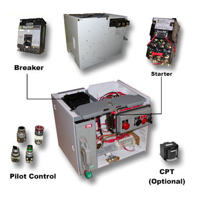
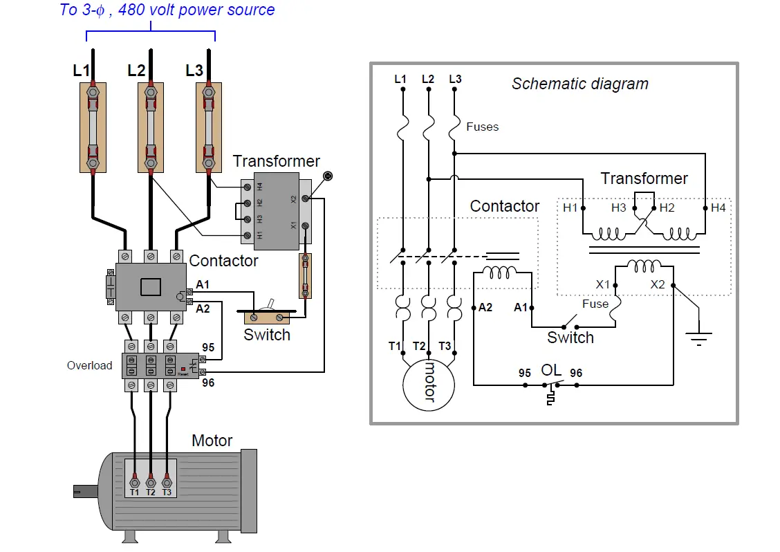
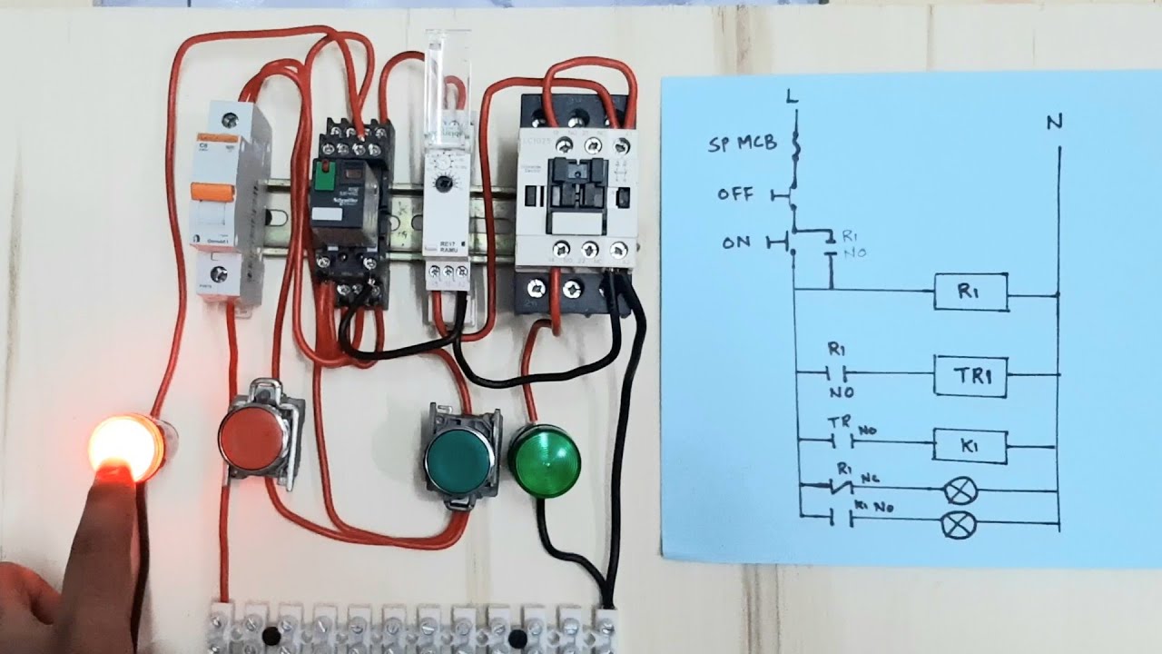
AC Motor Control Circuits Worksheet - AC Electric Circuits A very common form of latch circuit is the simple “start-stop” relay circuit used for motor controls, whereby a pair of momentary-contact pushbutton switches control the operation of an electric motor. In this particular case, I show a low-voltage control circuit and a 3-phase, higher voltage motor: Three Phase Motor Power & Control Wiring Diagrams Three Phase Motor Connection STAR/DELTA Without Timer - Power & Control Diagrams. Three Phase Motor Connection Star/Delta (Y-Δ) Reverse / Forward with - Timer Power & Control Diagram. Starting & Stopping of 3-Phase Motor from more than One Place Power & Control diagrams. Control 3-Phase Motor from more than Two buttons - Power & Control ... Mastering Motor Control Center (MCC): Wiring diagrams and ... Mastering Motor Control Center (MCC): Wiring diagrams and equipment from zero to hero An MCC comprises three buses for a three-phase system and the cabinet consists of a circuit breaker, a motor starter, and a control transformer; however, the actual contents vary widely as per requirements.
Motor control center wiring diagram. Motor Control Center Wiring Diagram | Electrical ... Motor Control Center Wiring Diagram | Electrical & Electronics with regard to Motor Wiring Diagram by admin Through the thousand photographs on the net about motor wiring diagram, we selects the very best libraries along with ideal quality only for you, and now this photos is one of photos selections in your greatest photographs gallery about Motor Wiring Diagram. Square D Mcc Bucket Wiring Diagram - schematron.org Section 1—About the Model 6 Motor Control Center 10 Section 4—Installing the MCC. that they agree with the wiring diagrams provided. the Mag-Gard or PowerPact selection tables in the Square D. Digest.Note: The Square D Model 6 Motor Control Center and buckets are no longer a current production item. Schneider Electric Wiring Diagram Book - Academia.edu This book contains examples of control circuits, motor starting switches, and wiring diagrams for ac manual starters, drum switches, starters, contactors, relays, limit switches, and lighting contactors. VW Fault Codes DTC - Car PDF Manual, Wiring Diagram ... My car is a 1989 Chrysler lebaron turbo. Can you please send me a wiring diagram for the ignition coil to the SMEC(engine computer)? Can you also send me the wiring diagram of the pick-up coil to the SMEC? . Thank you. Email freedomfrancisxxxx13@gmail.com. Thank you #197. Francois Tabi (Monday, 21 December 2020 00:01)
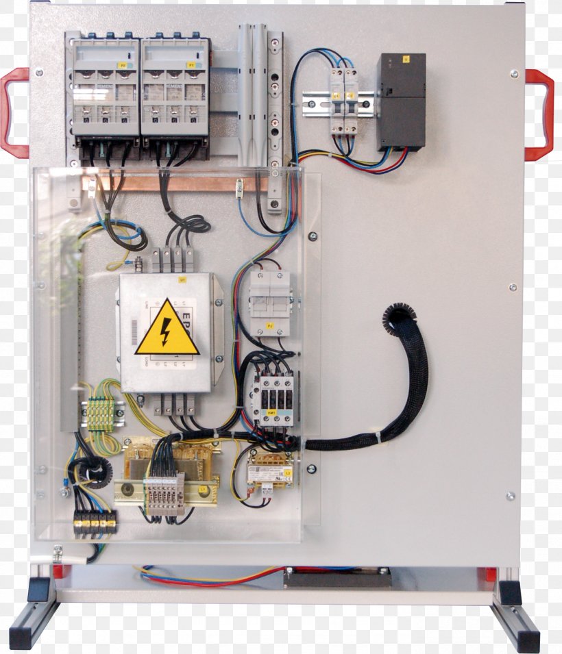
Motor Reversing Switch Wiring Diagram - Motor Wiring Diagram Collection of square d 2601ag2 wiring diagram. Forward reverse motor control diagram for 3 phase motor electrical online 4u electrical circuit diagram electrical diagram reverse. When you need to control a dc motor (such as a dc linear actuator) you usually need to be able to swap the polarity on the wires going to the motor. PDF Motor Control Centers - Elliott Electric Spectra SeriesTm/8000-Line Motor Control Centers Figure 1. Typical Spectra MCC motor control center with separate vertical wiring trough open on one section. Caution: Extreme care should be taken when servicing control wiring or removing units for any purpose from an energized control center since power from an external source may still be applied. PDF 7700-Line Motor Control Center 7700-Line Motor Control Center Ordering Instructions GEF-4628B 7700-Line Motor Control Center Section Nameplate (located on the front of each UL listed section, near the upper right-hand corner) When ordering replacement parts not identified in this bulletin, both the "CAT. NO." and "DIAGRAM NO." Basic wiring for motor control - Technical data guide | EEP Wiring diagrams, sometimes called " main " or " construction " diagrams, show the actual connection points for the wires to the components and terminals of the controller. Basic wiring for motor control - Technical data They show the relative location of the components. They can be used as a guide when wiring the controller.
Wonderful Motor Schematic Diagram Boat Trailer Wiring Three phase motor connection schematic power and control wiring installation diagrams. What is stepper motor driver. It shows the components of the circuit as simplified shapes and the power and signal connections between the devices. Figure 1 is a typical wiring diagram for a three phase magnetic motor starter. As this motor control. A ... PDF Motor control centers— low voltage - Eaton 12X of mounting space is available with a A suitable diagram illustrating operation of the control associated with the motor control center will be provided. When master terminal blocks are specified, the terminal arrangement and required wiring connections are shown on the diagram. NEMA Types of Wiring Motor Control Center Design Guide 600V - PAKTECHPOINT Motor Control Center Wiring Diagram MCC Structural Requirements Common Enclosure and Cubicle Design The vertical sections of MCC shall consist of one or more standardized sections, bolted together to form a rigid, self-supporting, free-standing assembly, with capability for addition of further sections to either end. Wiring Basics: Unipolar vs Bipolar - Oriental Motor U.S.A. Corp. The quick answer would be to follow the right wiring diagrams for the motor. First decide what wiring configurations are possible with your stepper motor, then find the right wiring diagram to follow. The diagrams below show the internal winding wiring diagrams for stepper motors with different numbers of lead wires.
File:Wiring diagram of motor control centre on pump station ...
Wiring Diagram Of Motor Control Center - Wiring Diagram Basic Wiring For Motor Control Technical Data Guide Eep. The wiring diagram and physical layout mastering motor control center mcc basic for basics of centers controls design www elmeccontractors com vintage replacement buckets ac circuits worksheet 1 cable electrical electronic drawing stp cb 3 5 phase panel reconditioned allen bradley 2100 series single motors low voltage mm300 protection ...
MM300 Motor Protection System :: GE Grid Solutions
Motor Control Center Explanation | MCC Panel wiring ... Motor Control Center Explanation | MCC Panel wiring diagram | MCC Panel | Control PanelHere in this video you will know about MCC or motor control center. Mo...

Motor Control Center Design Guide 600V | PAKTECHPOINT
AC motor control circuits - ibiblio wiring diagram calls for something different. It is your job to improvise a solution! file 00836 Question 4 Interpret this AC motor control circuit diagram, explaining the meaning of each symbol: L1 L2 Run M1 To 3-phase motor power source M1 Also, explain the operation of this motor control circuit. What happens when someone actuates the ...
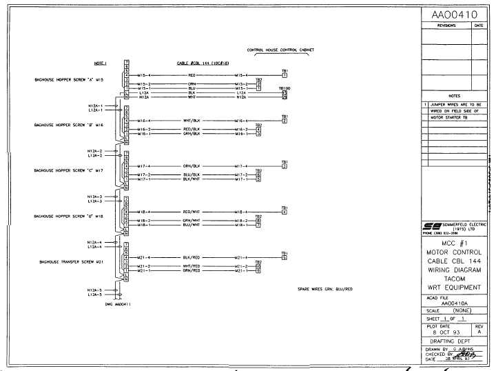
mcc #1 motor control cable wiring diagram
Arduino Servo Motor Basics and Control - Maker Portal Mar 20, 2020 · In the next section, another servo motor, the MG90S, will be used to demonstrate wiring and control of the servo with an Arduino board. Servo Wiring and Coding Basics with Arduino The MG90S is another small servo motor that is similar to the SG90, but weighs slightly more (14g) and has metal gears instead of plastic.
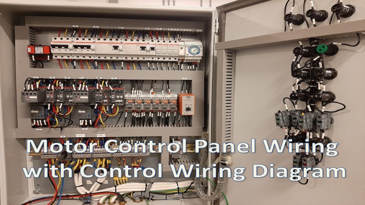
Motor Control Panel Wiring | Star Delta Connection | Motor Control Circuit | Panel Wiring Diagram
Low-voltage motor control centers documentation - Siemens USA Siemens motor control center wiring diagrams are at your fingertips within seconds. Use the tool below to quickly find and download one-line diagrams. E-House solutions - the fast-track project approach E-Houses are customized, pre-assembled, and pre-tested modular power substations. They are ideally suited for use in situations where fast ...
Buy Model 6 - Square D Motor Control Center
Fan Control Center Wiring Diagram - easywiring A wiring diagram is a straightforward visual representation from the physical connections and physical layout of your electrical system or circuit. Features transformer powers low voltage control systems and provides overload protection. Collection of fan control center wiring diagram.
How to Read a PLC Wiring Diagram (Control Panel Wiring ...
PDF 8000-Line/Spectra Motor Control Center - Patrick Enterprises 8000-Line/Spectra Motor Control Center Ordering Instructions 3 GEF-4628B 8000-Line/Spectra Motor Control Center Section Nameplate (located on the front of each UL listed section, near the upper right-hand corner) When ordering replacement parts not identified in this bulletin, both the "CAT. NO." and "DIAGRAM NO."
Distribution Board Wiring Diagram Motor Control Center Motor ...
Motor Control Center Wiring Diagram | Electrical diagram ... Motor Control Center Wiring Diagram. Edgefx Kits. 12k followers . Types Of Electrical Wiring ... Two Speeds One Direction Three Phase Motor Connection Power and Control Diagrams Abbreviations:O/L = Over Load RelayNO = Normally OpenNC = Normally CloseLow = Low SpeedHigh = High Seed 2 Speeds 1 Dire.

Electrical Engineering World - 88 Motor Control Wiring ...
Siemens Motor Control Center Wiring Diagram Download ... Siemens Motor Control Center Wiring Diagram Download. siemens motor control center wiring diagram - A Beginner s Guide to Circuit Diagrams An initial consider a circuit diagram might be confusing, yet if you can review a train map, you could read schematics. The purpose coincides: receiving from factor A to point B. Literally, a circuit is the…

Motor Control Center Explanation | MCC Panel wiring diagram | MCC Panel Wiring
Cutler Hammer Motor Starter Wiring Diagram - Wiring ... motor starter wiring diagrams - vintagemachinery.org knowledge base (wiki) - vintage machinery wiki starter for compressor motor | pirate 4x4 - pirate 4x4 motor starter diagram. start stop 3 wire control. starting a three phase motor. - youtube - youtube If you really want to be smarter, reading can be one of the lots ways to evoke and realize.

Reconditioned Allen Bradley 2100 Series Three Section MCC ...
PDF 16480 Motor Control Center B. Field wiring to the motor control center shall be tagged and shall terminate at the proper terminal blocks within the center. Wiring shall be run within the center wireways provided and shall be bundled and tied. Splices are not allowed within gutters or wireways. C. Provide a 4 inch high concrete pad for the motor control center.
Basic wiring for motor control - Technical data guide | EEP
PDF GI-2.0: Typical Wiring Diagrams - Rockwell Automation Wiring diagrams or connection diagrams include all of the devices in the system and show their physical relation to each other. All poles, terminals, coils, etc. are shown in their proper place on each device. These diagrams are helpful in wiring-up systems, because

Motor Control Center Explanation | MCC Panel wiring diagram ...
Wonderful Square D Mcc Bucket Wiring Diagram Autocad A wiring diagram is a simplified traditional pictorial depiction of an electric circuit. Square d mcc bucket wiring diagram. Click on the image to. Impt need a square d wiring diagram live plc questions and answers. As a matter of fact it probably took about 35 40 mins of being on the phone. Images of allen bradley mcc wiring diagrams ehero.
Schneider Electric Model 6 Motor Control Centers
Siemens Motor Control Center Wiring Diagram Download ... siemens motor control center wiring diagram - What's Wiring Diagram? A wiring diagram is a schematic which uses abstract pictorial symbols to exhibit all of the interconnections of components in a system.

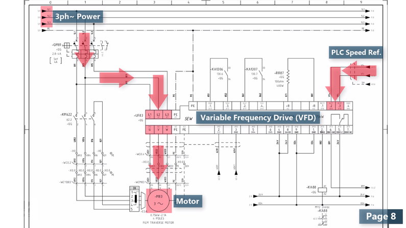
DC VARIABLE SPEED MOTOR CONTROL
Square D Mcc Bucket Wiring Diagram Download: Wiring Diagram Book - Square D Type NR Sockets,WELL- GUARD® Pump Panels,Definite Purpose Contactors ,Square D NEMA Relay. Section 1—About the Model 6 Motor Control Center .. 9. Schneider . Load and Control Wiring. that they agree with the wiring diagrams provided. the Mag-Gard or PowerPact selection tables in the Square D. Digest.

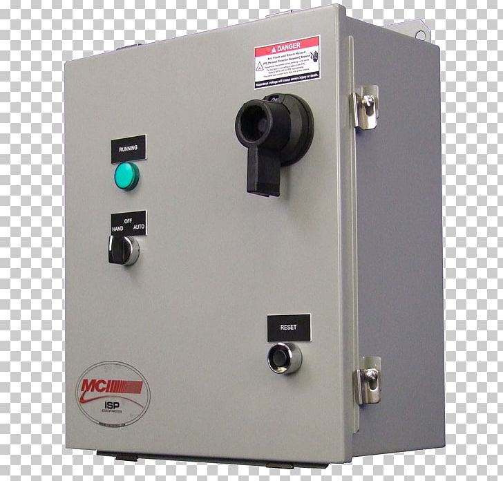
Motor Circuit Control Panel, Motor Protection Control Panel ...
Square D Motor Control Center Wiring Diagram Sample ... square d motor control center wiring diagram - What's Wiring Diagram? A wiring diagram is a schematic which uses abstract pictorial symbols to exhibit each of the interconnections of components in a system.

Square D Model 6 Motor Control Center 2 HP
Alternator Wiring Diagram: A Complete Tutorial | EdrawMax PCM Controlled Wiring Diagram Source: . The powertrain control module voltage regulation circuits are an advanced type of alternator that uses internal modules to control the field circuit of an alternator. The PCM regulates the current flow by examining the data from the body control module (BCM) and understanding the charging ...

Motor Control Centers Defined by Voltage, Configuration, Type ...
Basic Wiring Diagram for all Garden Tractors using a ... 05/09/2016 · Here is a basic wiring diagram that applies to all Vintage and Antique Lawn and Garden Tractors using a Stator Charging System and a Battery Ignition System. We did our best to keep this as simple and as easy to understand as possible. This applies to all old Cub Cadet, Ford, Jacobsen, John Deere, Wheel Horse, Case, and Simplicity Garden Tractors.

Motor Control Circuit Forward Reverse | Wiring and Connection ...
PDF Basic Wiring for Motor Contol - Eaton Basic Wiring for Motor Contol Circuitry of a Starter Two-Wire Control Two-Wire Control circuits — or Low Voltage Release One of the common control wiring circuits used is known as Two-Wire or Low Voltage Release (LVR). It utilizes a main-tained contact type of pilot device — such as a thermostat, float switch or presence sensor. Figure 6
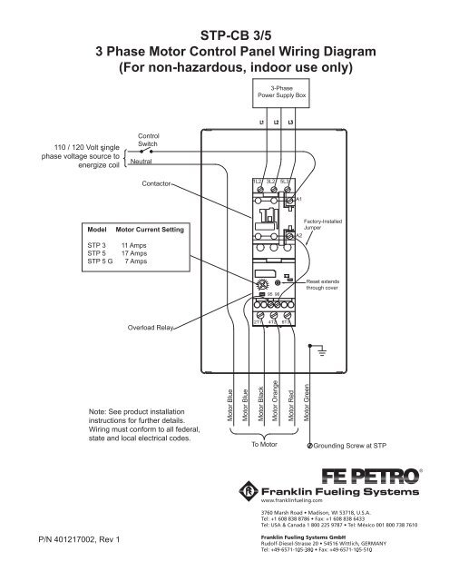
STP-CB 3/5 3 Phase Motor Control Panel Wiring Diagram ...
Great Motor Control Wiring Diagram Pdf 30a Rv Plug Basic wiring for motor control technical data. Motor control wiring diagram pdf. A2 14 18. Wiring diagrams show the connections to the controller. Learning 101 basics of motors and motor controls pdf version 1 created by noshea on sep 27 2012 8 52 am. They show the relative location of the components.

Electrical and electronic drawing--Industrial Controls
Motor Control Circuits | Motor Control Wiring Diagrams ... Summary : Motor contactor (or "starter") coils are typically designated by the letter "M" in ladder logic diagrams. Continuous motor operation with a momentary "start" switch is possible if a normally-open "seal-in" contact from the contactor is connected in parallel with the start switch, so that once the contactor is energized it maintains power to itself and keeps itself ...

MCC C CENTR | Instrumentation and Control Engineering
Mastering Motor Control Center (MCC): Wiring diagrams and ... Mastering Motor Control Center (MCC): Wiring diagrams and equipment from zero to hero An MCC comprises three buses for a three-phase system and the cabinet consists of a circuit breaker, a motor starter, and a control transformer; however, the actual contents vary widely as per requirements.
Siemens tiastar Motor Control Center (MCC)
Three Phase Motor Power & Control Wiring Diagrams Three Phase Motor Connection STAR/DELTA Without Timer - Power & Control Diagrams. Three Phase Motor Connection Star/Delta (Y-Δ) Reverse / Forward with - Timer Power & Control Diagram. Starting & Stopping of 3-Phase Motor from more than One Place Power & Control diagrams. Control 3-Phase Motor from more than Two buttons - Power & Control ...
Motor Control Circuit Wiring - Inst Tools
AC Motor Control Circuits Worksheet - AC Electric Circuits A very common form of latch circuit is the simple “start-stop” relay circuit used for motor controls, whereby a pair of momentary-contact pushbutton switches control the operation of an electric motor. In this particular case, I show a low-voltage control circuit and a 3-phase, higher voltage motor:

Double Motor Control with selective switch wiring connection ...
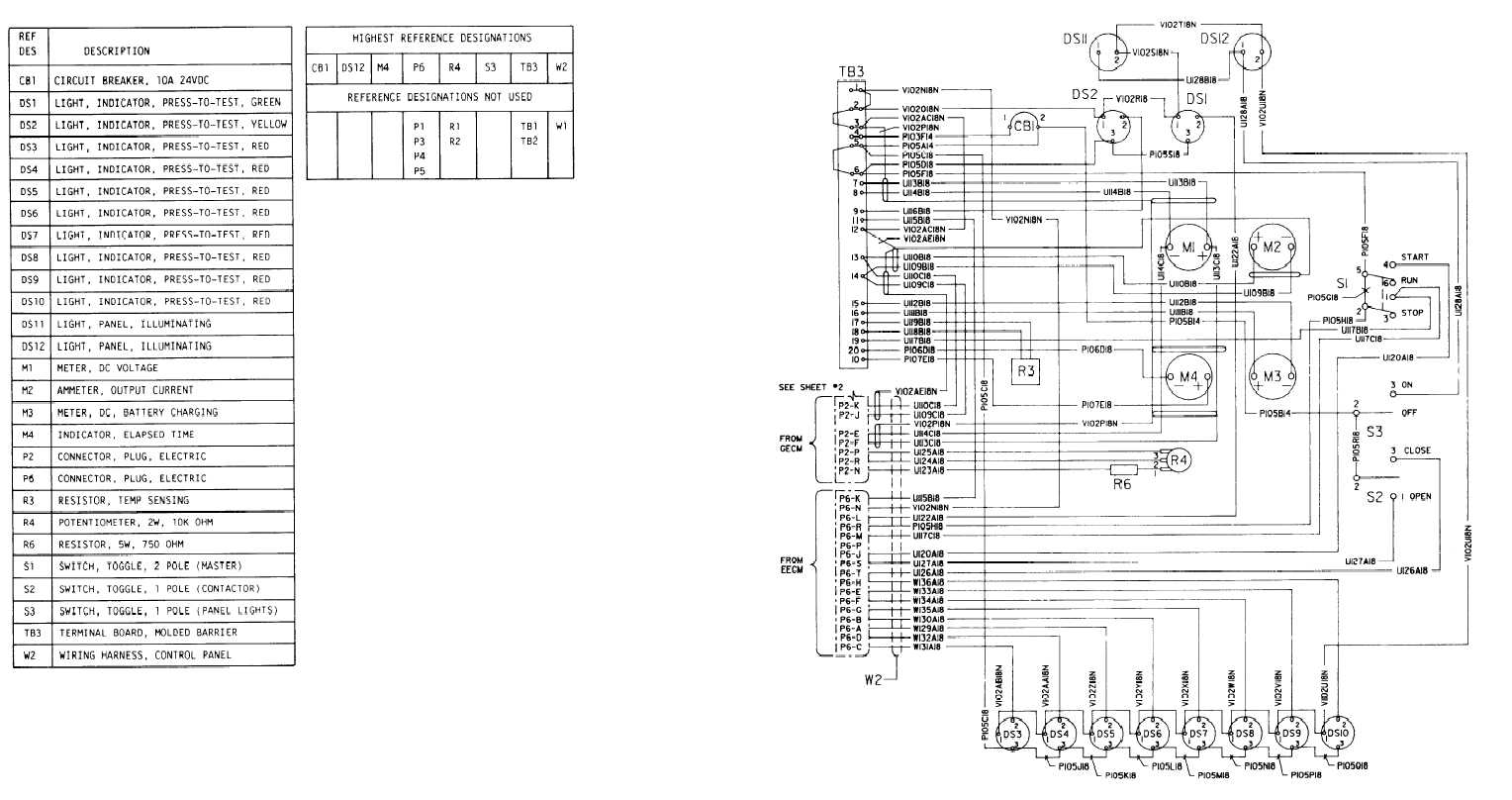
FO-4. Control Panel Wiring Diagram

NEMA ICS 2.3 1995 Instruction for Handling, Installation ...
Mastering Motor Control Center (MCC): Wiring diagrams and ...

Motor Control Circuit Forward Reverse | Wiring and Connection ...

File:Wiring diagram of motor control centre on pump station ...

How to start Motor feeder from MCC panel and wiring diagram

MCC Aftermarket Solutions
The Basics of Motor Control Centers (MCCs) | EEP
Circuit Breaker Car Wiring Diagram Electric Motor Tachometer ...

CONTROLS DESIGN - www.elmeccontractors.com
Motor Control Center Explanation | MCC Panel wiring diagram ...
Model 6 Motor Control Centers - Guillevin Industrial ...

DOL Starter Connection and Wiring Diagram with OLR - ETechnoG
0 Response to "38 motor control center wiring diagram"
Post a Comment