36 consider the circuit in the diagram
Electric Circuit - Diagram, Symbol, Open and Closed Circuit - Teachoo Let's consider a circuit diagram with open and closed switch. When we close the switch, the bulb glows. Extra Question 10 - A child has drawn the electric circuit to study Ohm's law as shown in Figure 12.6. His teacher told that the circuit diagram needs correction. Series RLC Circuit and RLC Series Circuit Analysis The phasor diagram for a series RLC circuit is produced by combining together the three individual phasors above and adding these voltages vectorially. The phase angle, θ between the source voltage, VS and the current, i is the same as for the angle between Z and R in the impedance triangle.
RLC Series AC Circuits | Physics Draw the circuit diagram for an RLC series circuit. Explain the significance of the resonant frequency. At resonance, the current is greater than at the higher and lower frequencies considered for the same circuit in the preceding example.
Consider the circuit in the diagram
Skill Builder: Reading Circuit Diagrams - Make Circuit diagrams, aka schematics, are line drawings that show how a circuit's components are connected together. They serve as a map or plan for Then you can test connections and otherwise debug and get to know the circuit with a multimeter, before you consider committing it to solder. Consider The Circuit In The Diagram - Wiring Site Resource Consider the circuit shown. Express all of your quantitative answers in terms of some or all of w x v andor b only. B firstly we know the voltage across two parallel branches is the Calculate the power delivered to each resistor in the circuit shown in figure p2131. Consider the following circuit diagram. PDF Recitation 6 (a) Draw a diagram of the circuit. (b) Calculate the unknowns and identify the physical meaning of each unknown. (a) Looking at the three equations, we see that the Q Imax = RC = 1.96 A For those who are interested the derivation of Eqns. 21 and 23 is pretty straightforward. Consider the circuit. I.
Consider the circuit in the diagram. How to Read Electrical Schematics - Circuit Basics An electrical schematic is a diagram that shows how all of the wires and components in an electronic circuit are connected. They're like a map for building or troubleshooting circuits, and can tell you almost Power sources supply electrical energy to a circuit in the form of voltage and current. PDF MasteringPhysics: Assignment Print View Part D Consider this diagram. Let us assume that it describes a series circuit containing a resistor, a capacitor, and an inductor. The current in the circuit has amplitude , as indicated in the figure. Which of the following choices gives the correct respective labels of the voltages across the resistor... Types of Electrical Drawing and Diagrams - Electrical Technology The logic diagram does not show the electrical characteristics of a circuit such as current, voltage or power etc. it only represents the logical function of the circuit or device where the signal is considered in binary format i.e. 1 or 0. Logic diagram are commonly used in digital logic designing. Example Diagram of Circuits | Quizlet Tips on drawing circuit diagrams. Use circuit symbols instead of drawing each component in the circuit. Always make the wires straight lines, and When drawing a circuit diagram from scratch, it's usually easier to draw the circuit symbols first, and then add all the wires. However, if you have to...
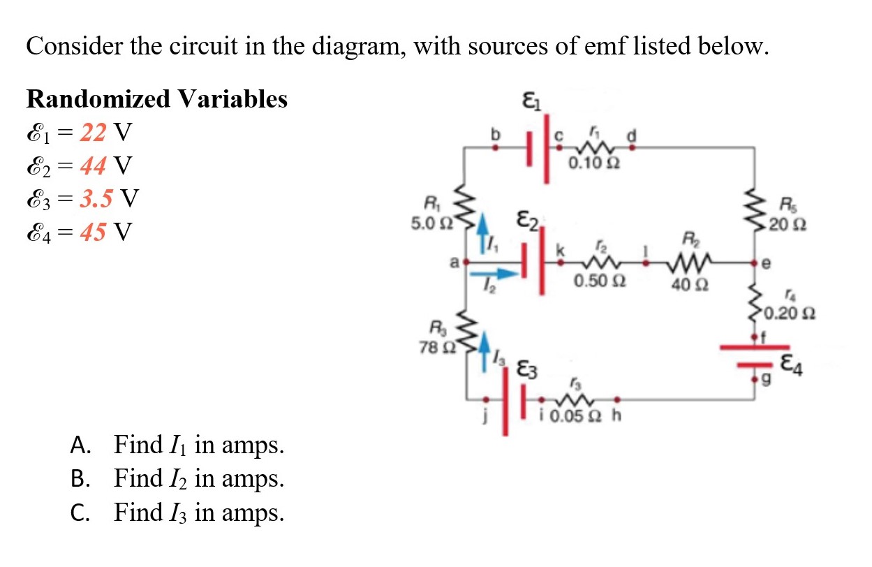
Series RLC Circuit — Collection of Solved Problems Drawing a phasor diagram for a series circuit We consider the fact that the phasors rotate in a counter clockwise direction. In the figure, this phasor is represented by yellow. We determine the size of the phase difference between the voltage and the current in the circuit from the phase diagram Consider the circuit in the diagram, with sources of emf listed ... Consider the circuit in the diagram, with sources of emf listed below: E1= 27V E2=41V E3=7.5V... Your Answer: Post as a guest. Your Name: What's your source?1 answer · Top answer: I1 = -0.21 A I2 = 0.22 A IS = I1+I2 = 0.01A 270 60.lon LI II Egon ww 1 410 0.son to for 3o. 2o1 L-I 78r 34 13 = (1, +12) CAT 39v 17.50 I o.oor loop ... Physics Tutorial: Circuit Symbols and Circuit Diagrams Some circuit symbols used in schematic diagrams are shown below. A single cell or other power source is represented by a long and a short parallel line. As an illustration of the use of electrical symbols in schematic diagrams, consider the following two examples. PDF Chapter 2: Circuit Elements In Circuit Analysis we will consider planar circuits only. Many of the techniques we learn here cannot be applied to non-planar circuits. All node voltages must be labeled just as they are in the diagram above. Those node voltages have a '+' sign at the non-reference node, and a '-' sign near the...
Consider the circuit shown in the diagram below. The battery ... Answer to: Consider the circuit shown in the diagram below. The battery has a voltage V = 12.0 V and the resistors have the following values: R1 =...1 answer · Top answer: We are given: • The battery voltage is Vb=12 VVb=12 V • The given resistances are: • R1=2.33 ΩR1=2.33 Ω • * {eq}R_2 = 4.66\... Circuit Diagram - Everything You Need to Know | EdrawMax Online Circuit diagram plays a vital role in the design, construction, and maintenance of electrical and electronic machinery. Equipment safety - Proper circuit diagrams assist the electrician in getting a better understanding of the design, considering modifications smartly, and adequately explain their... What is a Superposition Theorem? - Circuit Globe Considering the circuit diagram A, let us see the various steps to solve the superposition theorem: Step 1 - Take only one independent source of voltage or current and deactivate the other sources. Step 2 - In the circuit diagram B shown above, consider the source E1 and replace the other source E2... Simple Series Circuits | Series And Parallel Circuits | Electronics... In circuits containing more than one resistor, we must be careful in how we apply Ohm's Law. In the three-resistor example circuit below, we know that we have 9 volts between points 1 and 4, which is the amount of electromotive force driving the current through the series combination of R1, R2, and R3.
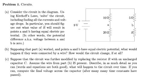
Solved Problem 1. Circuits. 105 9V (n) Consider the circuit ...
What is an Electrical Circuit? - Codrey Electronics | Circuit Diagram A circuit diagram is a visual display of an electrical circuit. There are mainly two types of circuit This load acts as a conductor path. If the current flows through the load it is considered as a closed Electric circuits are all around us, in our mobile phones, in our computers, in fan and also in the torch.
PD LD P R&D DTK Circuit diagram released Circuit diagram main ...
RLC Circuits (Alternating Current) | Brilliant Math & Science Wiki An RLC circuit contains different configurations of resistance, inductors, and capacitors in a circuit that is connected to an external AC current source. Io =LωVo . Looking at the term in the denominator, we infer that it acts as the resistance for this circuit and is known as Inductive reactance
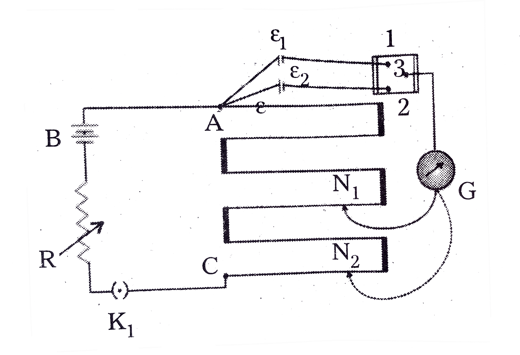
State the working principle of potentiometer explain with the ...
Electronic Circuit Symbols - Components and Schematic Diagram... Complete circuit symbols of electronic components. All circuit symbols are in standard format and can be used for drawing schematic circuit diagram Though these names are not approved as standard notations, they are commonly used by most people. These designations are also given in the list.
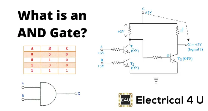
AND Gate: What is it? (Working Principle & Circuit Diagram ...
How to Read Circuit Diagrams for Beginners Circuit or schematic diagrams consist of symbols representing physical components and lines representing wires or electrical conductors. It is also necessary to understand how the components are connected together in the circuit. How to Read Circuit Diagrams for Beginners.

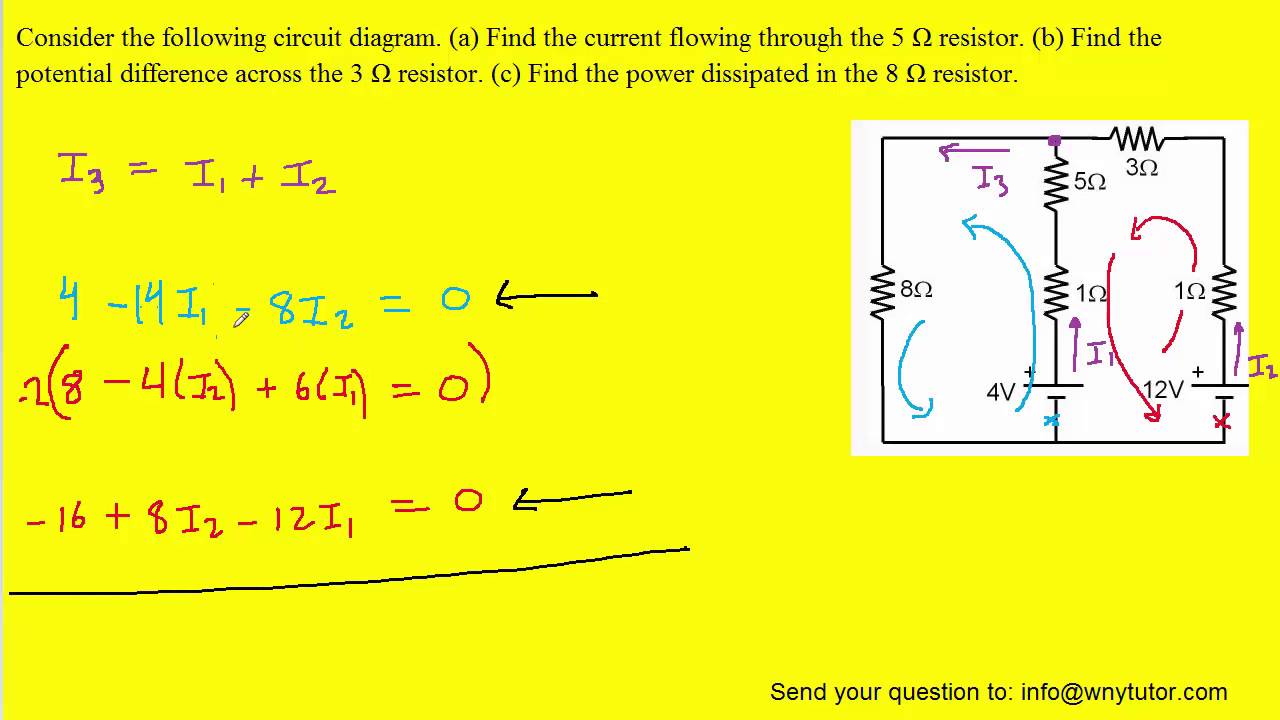
Consider the circuit shown in the diagram. Find the current ...
3: Logic Circuits, Boolean Algebra, and Truth Tables A logic diagram uses the pictoral description of logic gates in combination to represent a logic expression. An example below shows a logic diagram with three inputs (A, B, and C) and one output (Y). The interpretation of this will become clear in the following sections. TOPIC 4: Boolean Expression.

Consider the circuit shown in the diagram. Find the current ...
Consider the circuit shown in the diagram. Find the current in 3 ohm... In the circuit shown in figure, the potentials of B, C, and D are : Medium. View solution. > In a arrangement, 3n cells of emf ε and internal resistance r are > Use Kirchhoff's rules to determine the potential difference between the points A and D when no current flows in the arm BE of the electric...
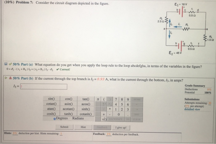
Solved (10%) Problem, 7: Consider the circuit diagram | Chegg.com
Circuit Diagram - Learn Everything About Circuit Diagrams A circuit diagram is a visual display of an electrical circuit using either basic images of parts or industry standard symbols. In conjunction with circuit diagram symbols, there are also a series of different types of line styles to connect objects. In the event lines cross, use line hops to show wire...

When the rms voltage VL,VC and VR are measured respectively ...
Direct Current Circuits To understand why, consider the circuit diagram in Active Figure 28.1a. The battery in this diagram is represented by the dashed rectangle containing an ideal, resistance-free emf in series with an internal resistance r. A resistor of resistance R is connected across the terminals of the battery.
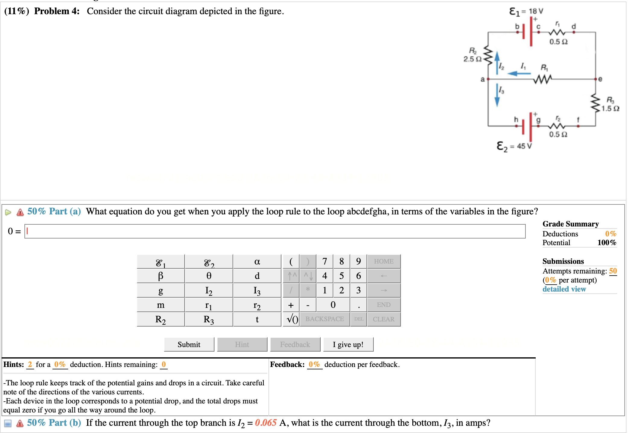
Solved (11%) Problem 4: Consider the circuit diagram | Chegg.com
Circuit diagram - Wikipedia A circuit diagram (wiring diagram, electrical diagram, elementary diagram, electronic schematic) is a graphical representation of an electrical circuit. A pictorial circuit diagram uses simple images of components...
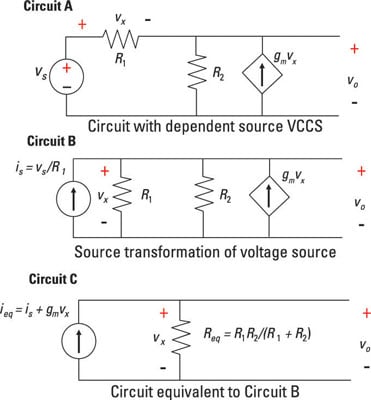
Analyze Circuits with Dependent Sources - dummies
3. Consider the circuit in the diagram below. What is | Chegg.com Physics questions and answers. 3. Consider the circuit in the diagram below. We review their content and use your feedback to keep the quality high. Transcribed image text: 3. Consider the circuit in the diagram below.
Solved: Consider the circuit in the diagram, (a) Draw the ...
Design and Analysis of Sequential Circuits We have spent some time considering combinational circuits. Combinational circuits are the basis of all digital devices, yet they do not suffice for any but the At this point, we have a complete description of the circuit. It may be possible to proceed from this diagram to obtain an understanding of what the...
Physics Tutorial: Series Circuits
Electronic Circuits - Quick Guide The circuit diagram of a low pass filter using RC and RL are as shown below. The frequency response of a practical filter is as shown here under and the frequency response of an ideal BPF when the practical considerations of electronic components are not considered will be as follows.
Circuit Diagram And Its Components - Explanation With Circuit ...
RLC Circuit Analysis (Series And Parallel) - Clearly... | Electrical4U In an RLC circuit, the most fundamental elements of a resistor, inductor, and capacitor are connected across a voltage supply. Phasor diagram of parallel RLC circuit, IR is the current flowing in the resistor, R in amps. Consider a RLC circuit having resistor R, inductor L, and capacitor C...
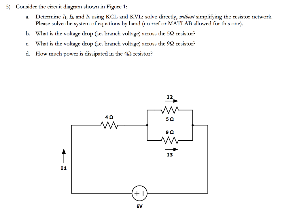
Solved 5) Consider the circuit diagram shown in Figure 1: a ...
PDF Recitation 6 (a) Draw a diagram of the circuit. (b) Calculate the unknowns and identify the physical meaning of each unknown. (a) Looking at the three equations, we see that the Q Imax = RC = 1.96 A For those who are interested the derivation of Eqns. 21 and 23 is pretty straightforward. Consider the circuit. I.
Physics Tutorial: Combination Circuits
Consider The Circuit In The Diagram - Wiring Site Resource Consider the circuit shown. Express all of your quantitative answers in terms of some or all of w x v andor b only. B firstly we know the voltage across two parallel branches is the Calculate the power delivered to each resistor in the circuit shown in figure p2131. Consider the following circuit diagram.
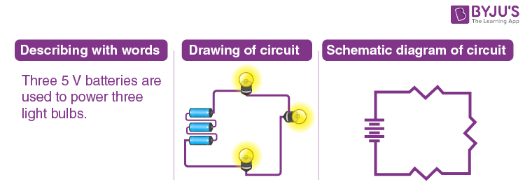
Circuit diagram - Simple circuits | Electricity and Circuits | Don't Memorise
Skill Builder: Reading Circuit Diagrams - Make Circuit diagrams, aka schematics, are line drawings that show how a circuit's components are connected together. They serve as a map or plan for Then you can test connections and otherwise debug and get to know the circuit with a multimeter, before you consider committing it to solder.

The circuit diagram given below shows the combination of ...

Time Constant Calculations Worksheet - DC Electric Circuits

Bipolartransistor Tutorial, Der BJT Transistor

Top 10 Best Circuit Diagram Makers of 2021 - My Chart Guide
Chapter 11 Circuits

Consider the circuit shown in the figure below

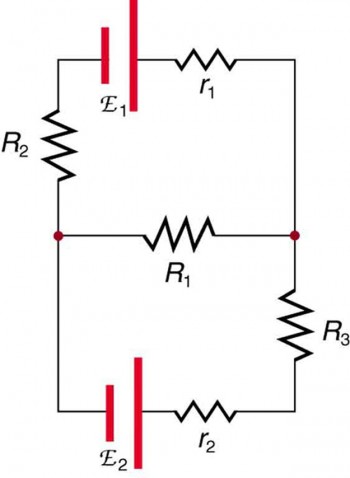
Consider the circuit in the diagram, with sources of emf ...
Practical Troubleshooting of Electronic Circuits for ...
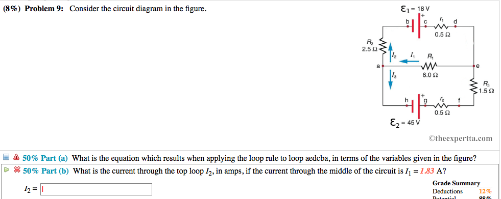
Solved (8%) Problem 9: Consider the circuit diagram in the ...
Kirchhoff's Rules | Physics

Consider the circuit diagram depicted in the figure. a. What ...
Consider the circuit shown in the figure below

Elektronischer Schutzschalter (787-2861/108-020) | WAGO AT
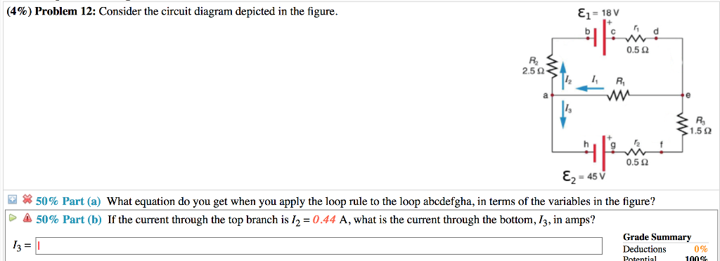
Solved (4%) Problem 12: Consider the circuit diagram | Chegg.com
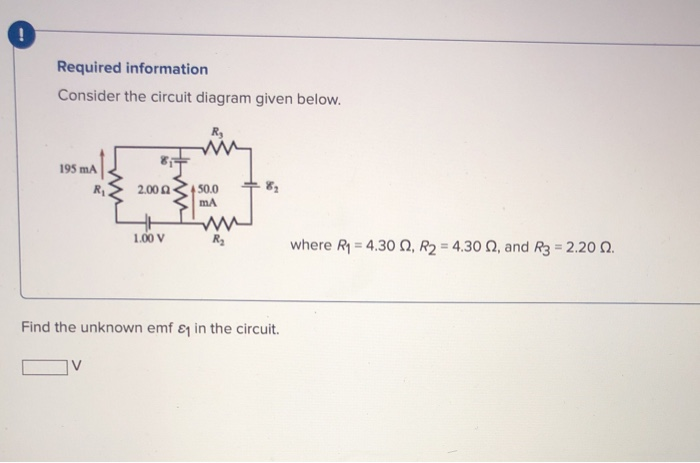
Solved Required information Consider the circuit diagram ...
Consider the following circuit diagram
How to find the total resistance of this circuit diagram - Quora
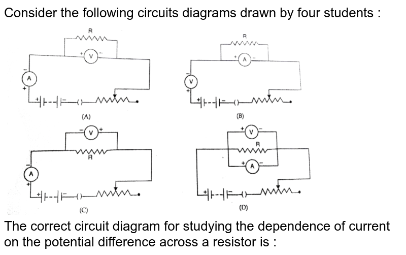
Draw a labelled circuit diagram to study the dependence of curren
Answered: Consider the circuit in the diagram,… | bartleby
6.3 Kirchhoff's Rules – Introduction to Electricity ...
0 Response to "36 consider the circuit in the diagram"
Post a Comment