38 petroleum refinery process flow diagram
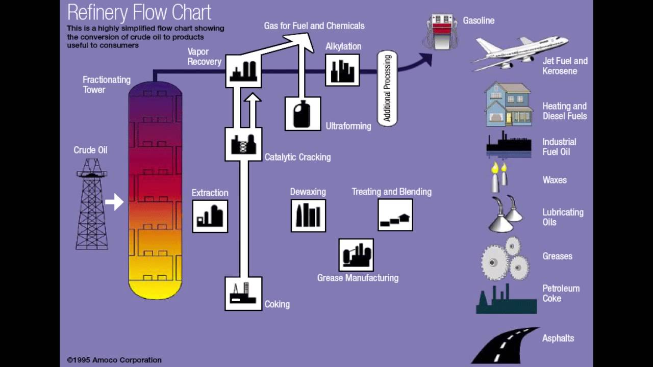
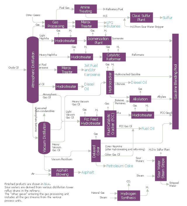
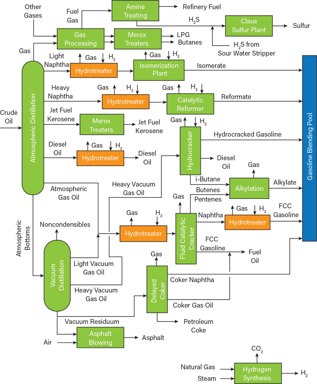
Flow diagram of a typical petroleum refinery. The image below is a schematic flow diagram of a typical petroleum refinery that depicts the various refining processes and the flow of intermediate product streams that occurs between the inlet crude oil feedstock and the final end-products. The petroleum refining industry employs a wide variety of processes. A refinery’s processing flow scheme is largely determined by the composition of the crude oil feedstock and the chosen slate of petroleum products. The example refinery flow scheme presented in Figure 5.1-1 shows the general
petroleum refining industry (SIC 2911, NAICS 32411). In response to this large number of fatal or catastrophic incidents, OSHA initiated CPL 03-00-004, the Petroleum Refinery Process Safety Management National Emphasis Program (NEP), in June 2007.3 The purpose of the NEP was to verify refinery employers’ compliance with PSM.
Petroleum refinery process flow diagram
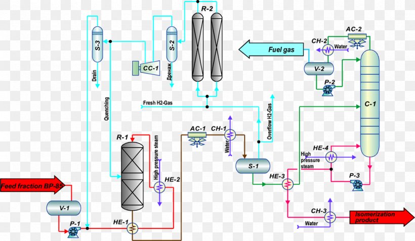
10 Application Solutions Guide — Refinery Process GLOBAL REFINERY LANDSCAPE Figure 1.4: In-process refinery end products and finished marketable refinery end products diagram API for valves The oil and gas industry does not use a universal API specification for valves like they have on … topic discussed:Process flow diagram of refinery.---CHEMICAL ENGINEER Thank You for watching the video....Like, share and subscribe to the channel... Find us... The image below is a schematic depiction of the equipment and the process flow streams in a typical refinery HDS unit: The liquid feed (at the bottom left in the diagram) is pumped up to the required elevated pressure and is joined by a stream of hydrogen-
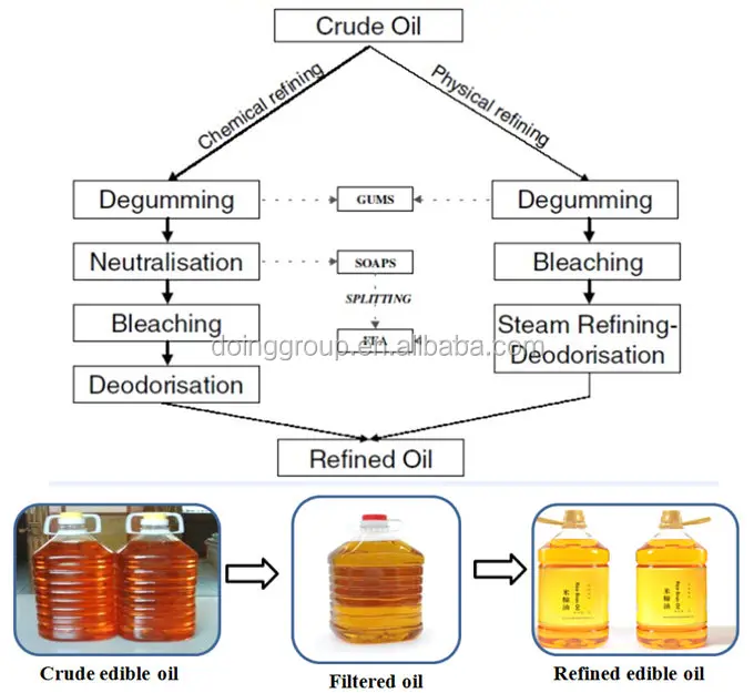
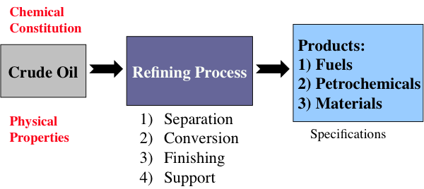
Petroleum refinery process flow diagram. Petroleum Refining is defined as the industrial process of production of useful petroleum products from crude oil. The plant where the useful products are separated from crude oil is known as a petroleum refinery. Crude oil or petroleum consists of various hydrocarbons. The crude oil refining process breaks the crude oil down into various components to make useful new products. Crude Oil Refinery Flow Diagram Showing Process Chemical Additives Financial benefits Whether it be extending equipment life due to corrosion inhibition, increasing production output due to enhanced deposit control, or shortening the the start-up time during sulphidation operations, we have resolved to provide you An oil refinery or petroleum refinery is an industrial process plant where petroleum (crude oil) is transformed and refined into useful products such as gasoline (petrol), diesel fuel, asphalt base, fuel oils, heating oil, kerosene, liquefied petroleum gas and petroleum naphtha. Petrochemicals feedstock like ethylene and propylene can also be produced directly by cracking crude oil without the ... Process. Petroleum refinery activities including use, storage, manufacturing, handling, piping or on-site movement that involve a highly hazardous material. Utilities and process equipment shall be considered part of the process if in the event of a failure or malfunction they could potentially contribute to …
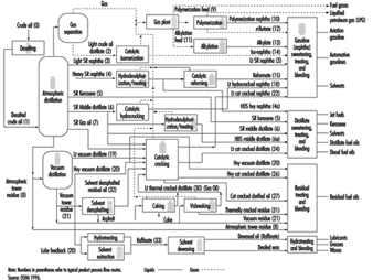
A flow diagram integrating the four types of processes in a petroleum refinery. Source: Dr. Semih Eser Separation processes, such as distillation, dewaxing, and deasphalting make use of the differences in the physical properties of crude oil components to separate groups of hydrocarbon compounds or inorganic impurities, whereas conversion ... Petroleum Refinery Process Create Process Flow Diagram examples like this template called Petroleum Refinery Process that you can easily edit and customize in minutes. 2/16 EXAMPLES Mar 01, 2008 · Leaching process flow diagram. The regeneration of spent leaching agent takes place in any one of the three leaching agent regenerators (02V02A/B/C). The regenerated leaching agent is stored in the regenerated leaching agent tank (02TK03) from where it is pumped to 02TK04 for mixing with makeup leaching agent for recycling. Jul 05, 2012 · A crude oil refinery is a group of industrial facilities that turns crude oil and other inputs into finished petroleum products. A refinery's capacity refers to the maximum amount of crude oil designed to flow into the distillation unit of a refinery, also known as the crude unit.. The diagram above presents a stylized version of the distillation process.
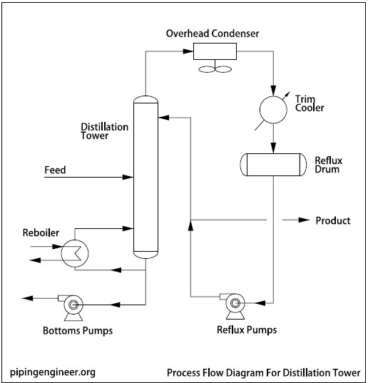
Natural Gas Industry Process Flow Diagram. Edit this example. Petroleum Refinery Process. Edit this example. Solar Heating - Direct Pumped System. Edit this example. Oil Refining - Extraction Process Diagram. Edit this example. Oil Industry Process Flow Diagram. Edit this example. Petroleum Refinery Process Economics, 2nd ed. , by Robert E. Maples, PennWell Corp., 2000 75 blends 135 blends a 1 0.03224 0.03324 a 2 0.00101 0.00085 a 3 0 0 b 1 0.04450 0.04285 b 2 0.00081 0.00066 b 3-0.00645 -0.00632 A Process Flow Diagram (PFD) is a diagram which shows the relationships between the main components in a system. Process Flow Diagrams are widely used by engineers in chemical and process engineering, they allows to indicate the general flow of plant process streams and equipment, helps to design the petroleum refineries, petrochemical and chemical plants, natural gas processing plants, and ... REFINERY— PROCESS FLOW DIAGRAMS 5 Process Flow Diagrams — Refinery Conversion Process — Typical Distillation Unit Process Desciptions One of the other feedstocks to a refinery is hydrogen, which can be used in a hydrotreater, isomerization, FCC, reformer, and a complex, capital-intensive unit.
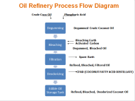
Rice Bran Oil Refining Machine Working Process Flow Chart Buy Rice Bran Oil Refining Machine Rice Bran Oil Refining Process Refined Rice Bran Oil Machine Price Product On Alibaba Com
the soybean processing industry and a description of the refining of edible soybean oil. The review of NOPA diagrams consisted of a discussion of process flow diagrams previously submitted . to . EPA by NOPA. Copies of the annotated diagrams are attached to this memorandum. A. General Information Generally, the soybean industry annually ...
Oil Refinery Process Flow Diagram Mt Makiling International Oil Inc
The image below is a schematic depiction of the equipment and the process flow streams in a typical refinery HDS unit: The liquid feed (at the bottom left in the diagram) is pumped up to the required elevated pressure and is joined by a stream of hydrogen-

Oil Refinery Petroleum Refining Processes Process Flow Diagram Harsh Times Angle Text Png Pngegg
topic discussed:Process flow diagram of refinery.---CHEMICAL ENGINEER Thank You for watching the video....Like, share and subscribe to the channel... Find us...
What Is Process Flow Diagram Edrawmax Online
10 Application Solutions Guide — Refinery Process GLOBAL REFINERY LANDSCAPE Figure 1.4: In-process refinery end products and finished marketable refinery end products diagram API for valves The oil and gas industry does not use a universal API specification for valves like they have on …

Refinery Process Flow Diagram Chemical Engineering World Facebook
An Overview Of Refinery Products And Processes Fsc 432 Petroleum Refining
Fsc 432 Refinery Flow Chart Youtube
Process Flow Diagram Typical Oil Refinery
2
2

Palm Kernel Oil Refining Plant Palm Oil Mill Machines
Block Flow Diagram Of A Typical Oil Refinery 30 P 35 Download Scientific Diagram

Oil Refinery Process Flow Diagram Culture Business Petroleum Png Clipart Brand Business Commlab India Communication Culture
Petroleum Refining Process

Figure 6 From Petroleum Refining Process Control And Real Time Optimization Semantic Scholar

Palm Oil Refinery
Process Diagrams Process Flow Diagram Typical Oil Refinery Flowchart For Production Of Kerosene

Scielo Brasil A Planning Model For Petroleum Refineries A Planning Model For Petroleum Refineries
An Overview Of Hydrotreating Aiche

Downstream Oil Gas
What Is The Vegetable Oil Refining Process Edible Oil Expeller Machinery
Texas City Refinery Explosion Oil Refinery Isomerization Petroleum Refining Processes Png 1024x596px Oil Refinery Area Diagram

Palm Oil Refining Process Flow Chart Edible Oil Palm Oil Oil Refinery
12 Flow Chart Of Refining Process Walnut Oil Production Line Products Anyang Gongke Grain And Oilmachinery Co Ltd

Process Flow Sheets Edible Oil Refinery Process Flow Sheet
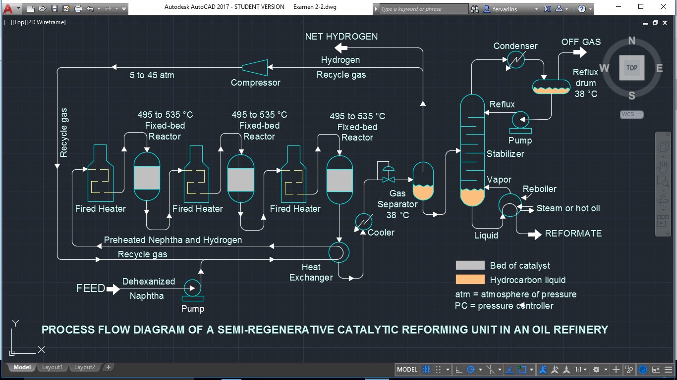
Fernanda Valdez On Twitter 2017bedepqex22 Process Flow Diagram Of A Semi Regenerative Catalytic Reforming Unit In An Oil Refinery Https T Co Krrn3nitbn Twitter
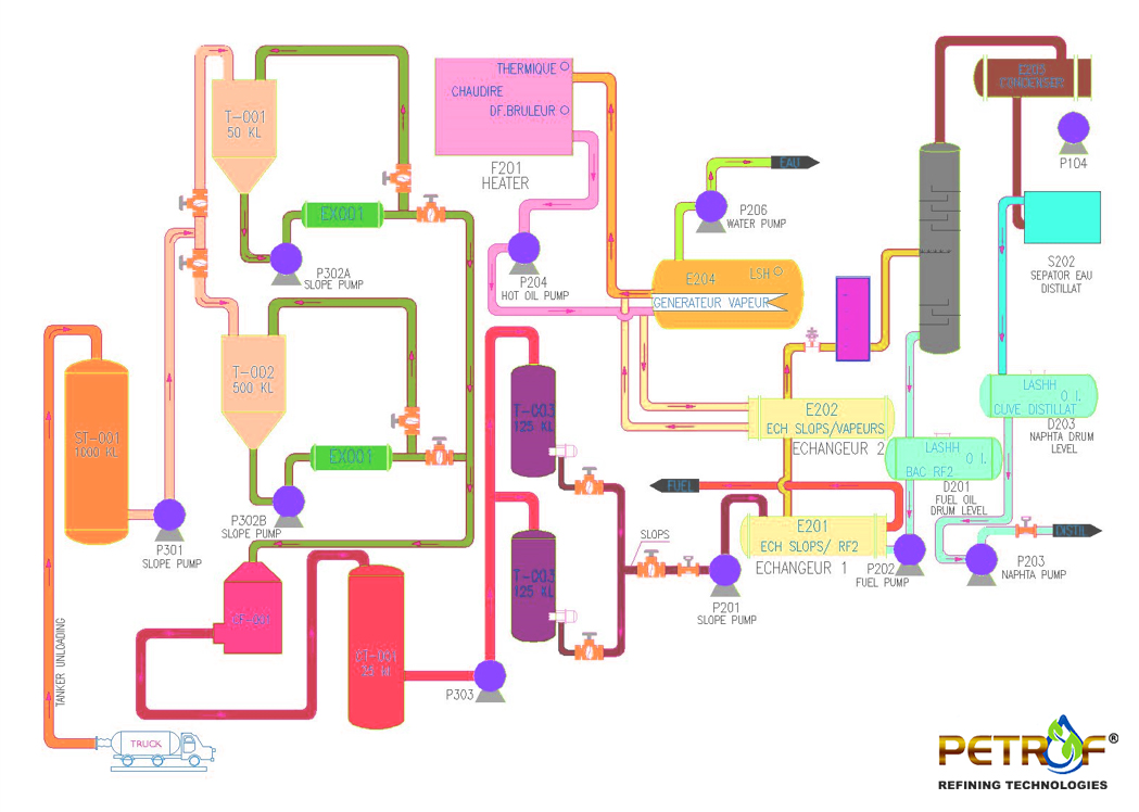
Process Flow Diagram Petrof Refining Technologies

Simplified Flow Chart Of Crude Oil Refinery Processes Download Scientific Diagram
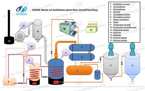
Crude Oil Refinery Process Flow Diagram Waste Oil Distillation Plant

Schematic Flow Chart Of A Modern Refinery Download Scientific Diagram

Oil Refinery Sugar Refinery Petroleum Refining Processes Process Flow Diagram Sm Prime Holdings Plan Engineering Png Pngegg

Engineer Darwing Refinery Of Crude Oil Flow Chart With Many Energy Fuel Product Stock Photo Picture And Royalty Free Image Image 13241751

Oil Refinery Petroleum Refining Processes Process Flow Diagram Harsh Times Angle Text Plan Png Pngwing
2

Oil Refinery Process Flow Diagram Petroleum Refining Processes Refinery Angle Text Png Pngegg

Crude Oil Refining Process Flow Enggcyclopedia

Coker Unit Delayed Coker Process Flow Diagram Oil Refinery Technology Angle Electronics Text Png Pngwing
2
0 Response to "38 petroleum refinery process flow diagram"
Post a Comment