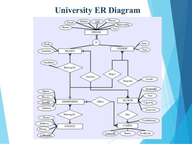
36 er diagram for university
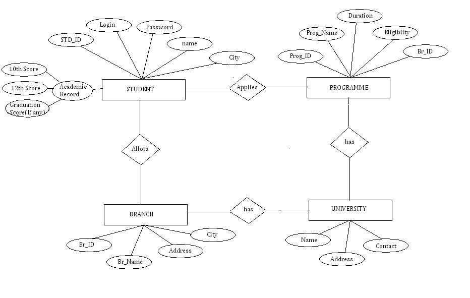
This is another ER diagram for the university database. This ERD is more program-oriented. It focuses more on the student information and the programs they have enrolled in. Covering the academic side of the database, this ERD will collect data to track each student’s performance. Example 3 Here’s another template for creating your ERD for university. This ERD covers multiple users like ... Design and draw an ER diagram that captures the information about the university. Use only the basic ER model here, that is, entities, relationships, and attributes. Be sure to indicate any key and participation constraints. Answer 2.3 The ER diagram is shown in Figure 2.1.
07.10.2021 · ER Diagram stands for Entity Relationship Diagram, also known as ERD is a diagram that displays the relationship of entity sets stored in a database. In other words, ER diagrams help to explain the logical structure of databases. ER diagrams are created based on three basic concepts: entities, attributes and relationships. ER Diagrams contain different symbols that use rectangles to represent ...

Er diagram for university
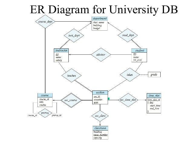
This ER (Entity Relationship) Diagram represents the model of University Management System Entity. The entity-relationship diagram of University Management System shows all the visual instrument of database tables and the relations between Students, Faculties, Colleges, Registrations etc. It used structure data and to define the relationships between structured data groups of University Management System functionalities. ER diagrams can be mapped to relational schema, that is, it is possible to create relational schema using ER diagram. We cannot import all the ER constraints into relational model, but an approximate schema can be generated. There are several processes and algorithms available to convert ER Diagrams into Relational Schema. Some of them are automated and some of them are manual. We may focus ... Entity-Relationship (ER) Diagrams Lecture 7 February 11, 2018 Entity-Relationship (ER) Diagrams 1. CS3200 –Database Design Spring 2018 Derbinsky Outline 1. Context – Design & Implementation Process 2. Goals of Conceptual Design 3. Entity-Relationship (ER) Model 4. One ER Diagrammatic Notation 5. Requirements Elicitation 6. Approaches to Conceptual Design February 11, 2018 Entity ...
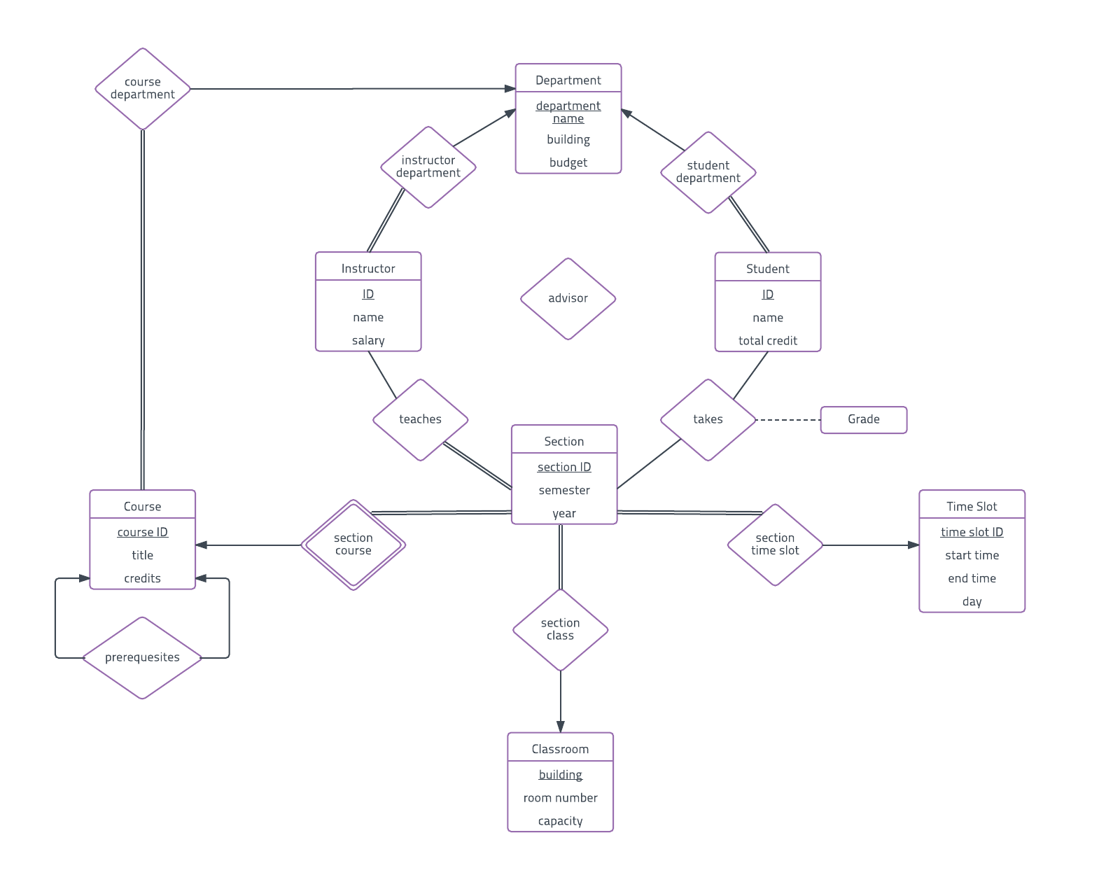
Er diagram for university. Follow the steps given below to draw an Entity Relationship (ER) diagram for a University database application −. Step 1 − Identifying the entity sets. The entity set has multiple instances in a given business scenario. As per the given constraints the entity sets are as follows −. Department. Course. Student. Instructor 27.09.2021 · ER Diagram Templates. Below are some ER diagram templates so you can get started quickly. Clicking on the image and in the new page that opens click the “Use as Template” button. For more templates check our ER diagram templates section. Transcribed image text: Q1 ER DIAGRAM FOR A UNIVERSITY DATABASE Consider the following set of requirements for a UNIVERSITY database that is used to keep track of students' transcripts. This is similar but not identical to the database shown in Figure 1.2 (a) The university keeps track of each student's name, student number, social security number, current address and phone, permanent address ... 10.03.2014 · The ER diagram represents the conceptual level of database design meanwhile the relational schema is the logical level for the database design. We will be following the simple rules: 1. Entities and Simple Attributes: An entity type within ER diagram is turned into a table. You may preferably keep the same name for the entity or give it a sensible name but avoid DBMS reserved …
A free customizable college ER diagram template is provided to download and print. The extensive built-in ER diagram symbols and professionally-created templates in Edraw help you start using the software quickly. You can choose appropriate symbols of ER diagram from the library, then drag and drop the symbols to create your diagram without effort. An Entity Relationship (ER) Diagram is a type of flowchart that illustrates how “entities” such as people, objects or concepts relate to each other within a system. ER Diagrams are most often used to design or debug relational databases in the fields of software engineering, business information systems, education and research. Also known as ERDs or ER Models, they use a defined set of ... ER Diagram of an University 2. Relational Schema For University Database (Underlined keys are primary Keys, and bold face keys are foreign keys) create table section ( SectionID int, course int, professor int, Name varchar (20), foreign key (Course) references course, foreign key (Professor) references professor. Original Title. Er Diagram For University Database – ER is really a substantial-level conceptual data design diagram. Entity-Connection version is dependant on the notion of real-world entities and also the relationship between the two. ER modeling allows you to evaluate details needs systematically to make a effectively-made data base.
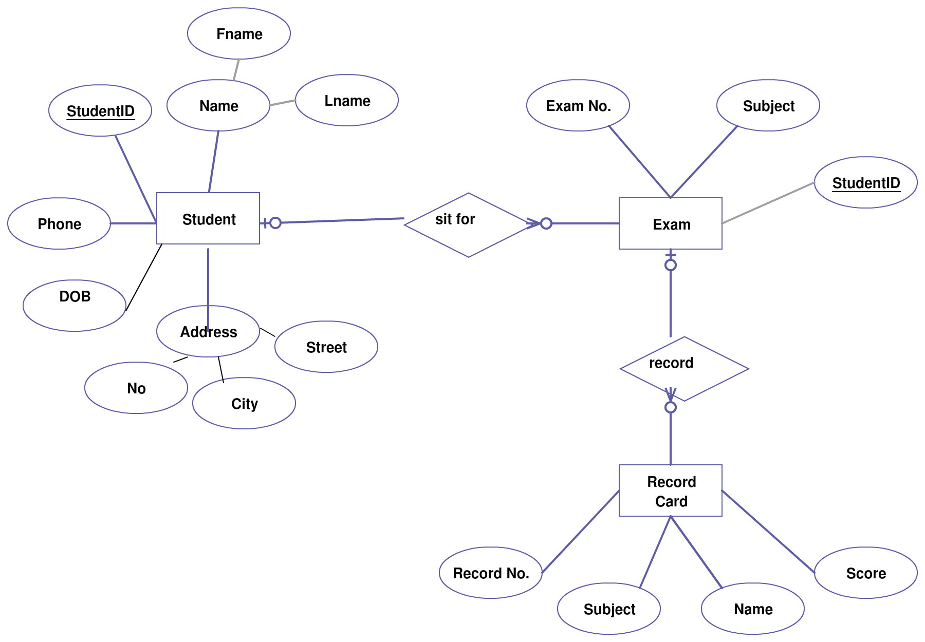
Looking for an online ERD diagram tool? Visual Paradigm's online ERD software makes database design fast and straight-forward. The ERD diagramming tool has all the ERD symbols and connectors you need to create professional, industry-standard ER model. No matter you want to create a conceptual, logical or physical data model, our online ERD tool just works perfectly. Draw an ER diagram for university database consisting of four entities. written 5.5 years ago by meghalikalyankar ♦ 730: modified 1 day ago by pedsangini276 ♦ 870: i. Student ii. Department iii. Class iv. Faculty and convert into tables. A student has a unique id and can enroll for multiple classes and has at most one major; This ER (Entity Relationship) Diagram represents the model of Railway Reservation System Entity. The entity-relationship diagram of Railway Reservation System shows all the visual instrument of database tables and the relations between Ticket, Customer, Train, Train Route etc. It used structure data and to define the relationships between structured data groups of Railway Reservation System ... Translation of ER -diagram into Relational Schema Dr. SunnieS. Chung CIS430/530. 2 Learning Objectives Define each of the following database terms Relation Primary key Foreign key Referential integrity Field Data type Null value 9.29.2 Discuss the role of designing databases in the analysis and design of an information system Learn how to transform an entity-relationship (ER) Diagram into an ...
Image from page 82 of "Practical physics" (1922)
Entity-Relationship (ER) Diagrams Lecture 7 February 11, 2018 Entity-Relationship (ER) Diagrams 1. CS3200 –Database Design Spring 2018 Derbinsky Outline 1. Context – Design & Implementation Process 2. Goals of Conceptual Design 3. Entity-Relationship (ER) Model 4. One ER Diagrammatic Notation 5. Requirements Elicitation 6. Approaches to Conceptual Design February 11, 2018 Entity ...

University Database Management System Er Diagram ...
ER diagrams can be mapped to relational schema, that is, it is possible to create relational schema using ER diagram. We cannot import all the ER constraints into relational model, but an approximate schema can be generated. There are several processes and algorithms available to convert ER Diagrams into Relational Schema. Some of them are automated and some of them are manual. We may focus ...

Web Gurus: ER Diagram for a College System Best Tutorials ...
This ER (Entity Relationship) Diagram represents the model of University Management System Entity. The entity-relationship diagram of University Management System shows all the visual instrument of database tables and the relations between Students, Faculties, Colleges, Registrations etc. It used structure data and to define the relationships between structured data groups of University Management System functionalities.

black bird on yellow hat
ER Diagram Examples and Templates | Lucidchart
Solved] Zip State City PPhone Birthdate Sex PAdress Class CPhone DegreeProgram CAdress DName DCode OfficeNum SSN SNum STUDENT (1,n) HAS MAJOR Office... | Course Hero

Image from page 132 of "Louis Napoleon, the destined monarch of the world and personal antichrist : foreshown in prophecy to confirm a seven years' covenant with the Jews about, or soon after 1863, and ... subsequently to become completely supreme over En
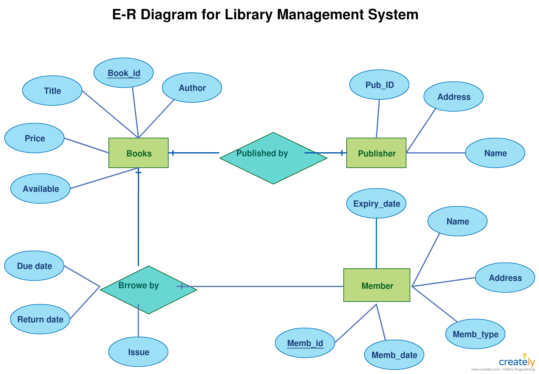
Er Diagram For Library Management System Of College ...

Dymaxion Car, Section (1933) // Richard Buckminster Fuller American, 1895-1983

Image from page 39 of "The Civil engineer and architect's journal, scientific and railway gazette" (1839)
ER diagram of Library Management System - GeeksforGeeks
Er Diagram Examples Of College | ERModelExample.com

University Database Management System Er Diagram ...

Marina City Theater, Chicago, Illinois, Roof and Partial Concrete Frame Development Drawing (1961-1962) // Bertrand Goldberg American, 1913-1997
An ER-Diagram illustrating 3 entities, Professors, Students, and... | Download Scientific Diagram

woman in white long sleeve dress and red scarf standing on concrete wall during daytime

green grass near body of water during daytime

Er Diagram For University Database | ERModelExample.com

woman beside grass

University Database ( Entity Relationship Diagram) | Creately

God Vishnu Measures the Universe in Three Strides (Trivikrama) (About 12th century) // India Odisha

, Library System Entity Relationship Diagram | Download ...
University Database ( Entity Relationship Diagram) | Creately
University er-diagram
Question 2:Identify all the associated entities for a University Management System, their corresponding attributes, relationships and cardinality and design an Entity-Relationship (ER) diagram for it. | MCA IGNOU GROUP

ERD Case Study | University Management System Part 1

unknown

white Roman temple during daytime
PDF] Mapping RDF and RDF-Schema to the Entity Relationship Model | Semantic Scholar
Er Diagram For University Admission System ...

Estatoe River Landscape (1984) // Evon Streetman American, born 1932

building near bare trees during winter

Er Diagram University Management System | ERModelExample.com
10287 lecture5(2)

selective-focus of brown and black building
Draw ERD for Online Admission System for a University ...
0 Response to "36 er diagram for university"
Post a Comment