38 copeland potential relay wiring diagram
danna-tonyo.com › archives › 2021-032021年03月 : うちの夫が糖尿病になっちゃった! | 食と血糖値・漫画ブログ Powered by... Mar 31, 2021 · 夫が2型糖尿病になってしまいました!3人の子どもを抱えた闘病生活を漫画(絵日記)で綴ります。糖尿病患者や予備軍の方の参考になるよう、お料理写真や血糖値・糖尿病の最新情報、生活習慣病に役立つ情報などを分かりやすくをモットーにお届けします! Copeland 3 Phase Compressor Wiring Diagram - U Wiring Copeland Potential Relay Wiring Diagram Run Capicator For Hvac Air Conditioning Electrical Diagram Air Conditioner Compressor . Contactor Wiring Diagram With Timer Diagram Relay Timer . Need Help Replacing Hvac Condensor Fan Motor 3 Wire Old To 4 Wire New Ceiling Fan Switch Ceiling Fan Wiring Fan Motor .
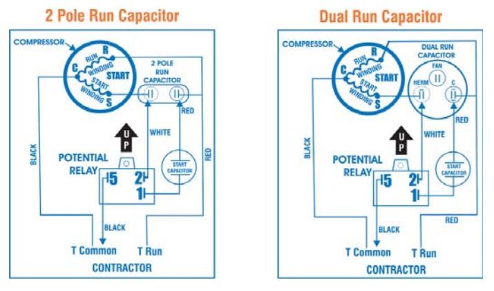
Copeland Compressor Wiring Diagram Copeland Compressor Wiring Diagram. accordance with the position of the capacitors and relay shown on the wiring diagram. Compressor model. Run capacitor. Start capacitor. Potential relay. MISWIRING IS MURDER. It is very easy to miswire a compressor, but the results can be deadly. The purpose of this booklet is to dem- onstrate how to wire a.

Copeland potential relay wiring diagram
Copeland To Mars Relay Cross Reference Guide The universal potential motor starting relay wiring diagram and cross reference. Permanent Leak Sealant That Saves Time And Money The Easy Way! Newbie s an instrument is applied with auxiliary switch: copeland cross reference and shoulder strap for free download copeland hermetically sealed compressors. Potential Relay Wiring Diagram - Wirings Diagram Potential Relay Wiring Diagram - compressor potential relay wiring diagram, copeland potential relay wiring diagram, mars potential relay wiring diagram, Every electrical arrangement consists of various distinct components. Each part should be set and connected with different parts in particular way. If not, the structure won't function as it should be. Copeland Scroll Compressor Wiring Diagram A/C Copeland Scroll® .. Compressor wiring diagrams with motor winding connec- Data-Copeland Scroll Compressors, and Electrical. Refer to original equipment wiring diagrams. Care must be taken to ensure that wiring or . The Copeland Scroll compressor's inherent. Copeland Scroll compressors have a voltage tolerance of + 10%.
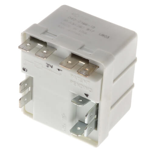
Copeland potential relay wiring diagram. PDF MARS Potential Relays MARS HVAC Potential Relays MARS series relays are manufactured for the HVAC industry. These relays meet all requirements for original equipment relays. Features: • 50/60 Hz • cULus • Contact rating 35 amp, 400 VAC • Operating position tab up • Instructions and wiring diagram included in each relay • Class "B" insulation C O M P ... PDF Section E Electrical Component Nomenclature and Data Topics Wholesaler Copeland® GE P/N Pick-up Drop Out Cont. Volt Freq. P/N Brand P/N Volts Volts Rating Potential Relay Data 940-0001-82 040-0166-39 3ARR3T3U5 220 - 240 40 - 90 332 60 bellavue-bikerbetten.de › pastor-bryan-crute-resignsbellavue-bikerbetten.de Feb 18, 2022 · During his high-school years, he starred in a variety of musical theater productions. Following. Bryan Ardis told "ReFounding America" host Dr. Bryan Crute Ретвитнул(а) Jordan Cronin. from The Master’s Seminary. Includes wiring diagram and mounting instructions! Brand New Aftermarket Solenoid Relay for Warn & Ramsey Winch Motors. Air Compressor Wiring Diagram 240v - Diagram Sketch Air Compressor Wiring Diagram 240v. Unique Wiring Diagram Ac Split Mitsubishi Refrigeration And Air Conditioning Hvac Air Conditioning Hvac Air. Copeland Potential Relay Wiring Diagram Run Capicator For Hvac Air Conditioning Air Conditioner Compressor Electrical Diagram. 0 75hp 110 220 Single Phase Motor Circuit Diagram Electrical Diagram ...
› 37299533 › AIR_CONDITIONING_AND(PDF) AIR CONDITIONING AND REFRIGERATION REPAIR MADE EASY ... Academia.edu is a platform for academics to share research papers. Copeland Potential Relay Wiring Diagram Copeland Potential Relay Wiring Diagram. Nov 12, of the relay to disconnect the start capacitor at a speed where the motor has Circuits. If there is a terminal in position #6, it must be the same polarity as terminals #1, MOTOR START POTENTIAL RELAY. 50 Amperes max. Sep 2, Figure 2 shows how a potential relay is wired to a capacitor-start ... Copeland Compressor Wiring Diagram Download - Wiring ... Size: 129.75 KB. Dimension: 1212 x 822. DOWNLOAD. Wiring Diagram Images Detail: Name: copeland compressor wiring diagram - Copeland Hvac Wiring Diagram Library Potential Relay At Imovo Psc Copeland Scroll pressor Wiring Diagram. File Type: JPG. Source: nhrt.info. Size: 179.43 KB. Dimension: 645 x 930. Wiring Diagram Symbols Relay - Wiring Sample Potential relay wiring diagram compressor potential relay wiring diagram copeland potential relay wiring diagram mars potential relay wiring diagram every electrical arrangement consists of various distinct components. Electrical symbols and smart connectors help present your electrical drawings electrical schematic wiring diagrams and blue prints.
Copeland Potential Relay 040 0166 19 Wiring | Wiring ... Potential Relay Wiring Diagram - compressor potential relay wiring diagram, copeland potential relay wiring diagram, mars potential relay wiring diagram, Every electric structure consists of various diverse pieces. Each part ought to be set and linked to other parts in particular way. If not, the structure won't work as it ought to be. Potential Relay Wiring Diagram - Wiring Diagram Copeland Potential Relay 040 0166 19 Wiring | Wiring Diagram - Potential Relay Wiring Diagram. You are able to often depend on Wiring Diagram as an important reference that may assist you to preserve money and time. With the assist of this e-book, you'll be able to very easily do your own personal wiring tasks. Compressor Potential Relay Wiring Diagram Compressor Potential Relay Wiring Diagram- One of the most hard automotive repair tasks that a mechanic or fix shop can give a positive response is the wiring, or rewiring of a car's electrical system.The hardship in reality is that all car is different. subsequent to a pain to remove, replace or repair the wiring in an automobile, having an accurate and detailed compressor potential relay ... Wiring Diagram Of A Potential Relay If you are looking for copeland potential relay 040 0166 19 wiring you have come to the perfect site. Instructions for wiring a standard automotive relay with descriptions of the pin out and the schematic. This is the wiring of the potential relay. Ribu1c wiring diagram lovely generous potential relay wiring diagram.
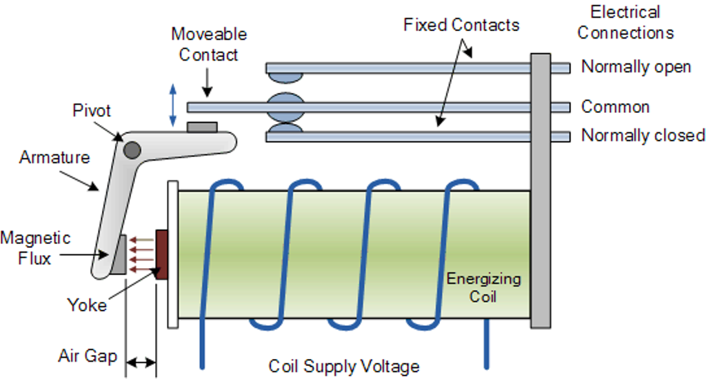
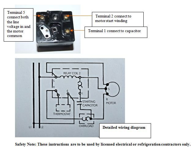
Diagram of the potential relay Part 2
Copeland Potential Relay Wiring Diagram Run Capicator For ... potential relay wiring diagram - You will need a comprehensive, expert, and easy to understand Wiring Diagram. With such an illustrative guide, you'll be capable of troubleshoot, avoid, and total your projects easily. Not just will it assist you to accomplish your desired outcomes faster, but additionally make the complete procedure easier for everyone.
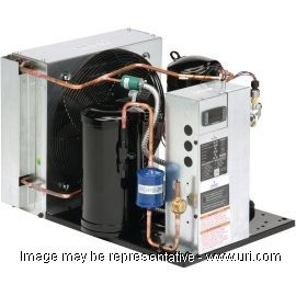
Shop FFAMA10ZCFV072 - Air Cooled Condensing Unit - Copeland - URI
Copeland Potential Relay Wiring Diagram - Wiring View And ... Copeland Potential Relay Wiring Diagram. Know your potential starting relays achr news 10 3 4 solid state and devices 5 motor bearings 6 drives components for electric motors what happened to terminal hvac p m relay model pm a3c2 air conditioning spare parts suppliers wholers in dubai copeland electrical handbook pdf doent basic controls of ...
Technical Information
PDF MARS Relays & Potential Relays • 2 relays replace over 25 O.E.M. relays • Universal break-off bracket on each relay. Simply snap off parts not needed • UL and CSA listings available One-On-One™ Direct Replacement Potential Relays The relays are exact replacements for Bristol & Copeland applications. They conform to specifications and in most cases are the one-on-one™

Potential for Good and Evil (The Hard Start & Potential Relay ...
Copeland Potential Relay Cross Reference The universal potential motor starting relay wiring diagram and cross reference. If Emerson fails to insist once or promise strict performance of any provision of this EULA, it shall not thereby impose any provision or right. ... Emf generated across terminals two types of copeland potential relay has some occasions a test relays plus tells you ...

30 Unique Refrigerator Start Relay Wiring Diagram- A control ...
Copeland Potential Relay Wiring Diagram Run Capicator For ... 55 New Potential Relay Wiring Diagram- A govern relay is used in the automotive industry to restrict and regulate the flow of electricity to various electrical parts inside the automobile. They permit a small circuit to direct a later flow circuit using an electromagnet to rule the flow of electricity inside the circuit. ... Copeland Condenser ...
How to Use Relays to Control High-Voltage Circuits with an ...
docshare.tips › carlson-foundations-of-behavioralCarlson Foundations of Behavioral Neuroscience 9th c2014 ... The membrane potential quickly returns to normal, but first it overshoots the resting potential, becoming hyperpolarized—more polarized than normal—for a short time. The whole process takes about 2 msec (milliseconds). (See Figure 14.) This phenomenon, a very rapid reversal of the membrane potential, is called the action po-tential.

Freshen BORN CHILL | Facebook
PDF Copeland compressor - Emerson Electric A - Hermetic Compressors Emerson Climate Technologies 2014DS-78 R2 (2/16)4 AF - Compressor Parts Model Start Capacitor Run Capacitor Current Relay Potential Relay Overload

Start Capacitor & Inrush Facts and Myths - Part #1 - HVAC School
Compressor Potential Relay Wiring Diagram - Wiring Sample Supco 9065 Potential Relay 35 A At 277 Vac Contact Rating 332 V. Copeland Potential Relay Wiring Diagram. Figure 3 CSIR motor diagram push-on current relay. Compressor Current Relay Wiring Diagram wiring diagram is a simplified satisfactory pictorial representation of an electrical circuit.
RELAY PROBLEMS
bjc.edc.org › June2020bjc2 › bjc-rbjc.edc.org data:image/png;base64,iVBORw0KGgoAAAANSUhEUgAAAKAAAAB4CAYAAAB1ovlvAAACs0lEQVR4Xu3XMWoqUQCG0RtN7wJck7VgEW1cR3aUTbgb7UUFmYfpUiTFK/xAzlQWAz/z3cMMvk3TNA2XAlGBNwCj8ma ...
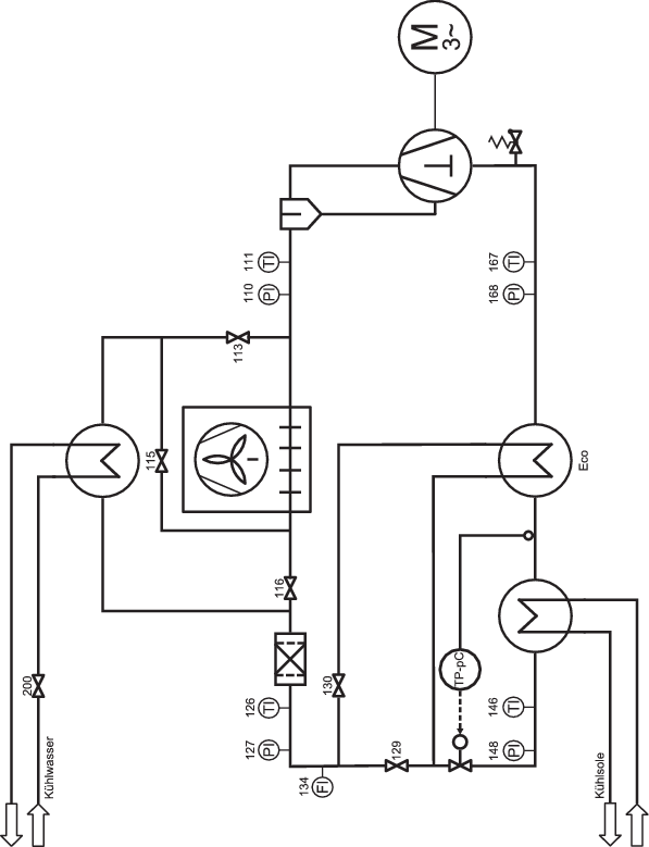
Kaltdampfverfahren | SpringerLink
potential relay wiring diagram - MetinSaksham Potential relay wiring diagram compressor potential relay wiring diagram copeland potential relay wiring diagram mars potential relay wiring diagram every electrical arrangement consists of various distinct components. When you make use of your finger or perhaps stick to the circuit together with your eyes it is easy to mistrace the circuit.
Potential Relay Kit
Potential Relay Wiring Diagram - Cadician's Blog Copeland Potential Relay 040 0166 19 Wiring | Wiring Diagram - Potential Relay Wiring Diagram. You are able to often depend on Wiring Diagram as an important reference that may assist you to preserve money and time. With the assist of this e-book, you'll be able to very easily do your own personal wiring tasks.

Potential Relays - What Happened to Terminal 3? | HVAC
en.wikipedia.org › wiki › History_of_computing_hardwareHistory of computing hardware - Wikipedia The Z2 was one of the earliest examples of an electromechanical relay computer, and was created by German engineer Konrad Zuse in 1940. It was an improvement on his earlier Z1 ; although it used the same mechanical memory , it replaced the arithmetic and control logic with electrical relay circuits.

Potential Relays - What Happened to Terminal 3? | HVAC
Copeland refrigeration manual part 2 - Australian manuals ... manual€copeland potential relay wiring diagram€copeland refrigeration manual part 2€copeland refrigeration manual serial 06d27035b€copeland scroll compressor Read and Download Copeland Refrigeration Manual Part 2 Free Ebooks in PDF format - CAPITAL BUDGETING PROBLEMS SOLUTIONS THE IT GIRL 1 CECILY VON ZIEGESAR ESSENTIAL ...

Single Phase Wire Diagrams
Wiring a Potential Relay, Bristol Copeland View and download abb vd4 instruction manual online. The relays with a diode suppressor will have polarity sensitive coil connections. Replaces wire-by-wire virtually any potential relay on the market. We have 21 pictures about copeland potential relay 040 0166 19 wiring including images, graphics, photos, pics, and much more.
Assembly Instructions
Diagram of the potential relay Part 2 - YouTube This is the wiring of the potential relay. This video is part of the heating and cooling series of training videos made to accompany my websites: ...

Electrical and Electronics Engineering: Air condition ...
PDF INSTRUCTION SHEET: RBM Wiring Diagram and Cross Reference. INSTRUCTION SHEET: The Universal Potential Motor Starting Relay Wiring Diagram and Cross Reference. RBM 90-63 Potential Relay Continuous Coil Voltage 170 Pick Up Minimum 140 Maximum 153 Drop Out Maximum 65 90-64 Potential Relay Continuous Coil Voltage 395 Pick Up Minimum 245 Maximum 275 Drop Out Maximum 140 90-65 Potential Relay Continuous Coil ...
AE-1423 1.5 to 5 Ton ZPS*K6 Copeland Scroll Two Stage Compressors
Copeland Scroll Compressor Wiring Diagram A/C Copeland Scroll® .. Compressor wiring diagrams with motor winding connec- Data-Copeland Scroll Compressors, and Electrical. Refer to original equipment wiring diagrams. Care must be taken to ensure that wiring or . The Copeland Scroll compressor's inherent. Copeland Scroll compressors have a voltage tolerance of + 10%.

Basic Electrical Controls of Air-Conditioning Units ...
Potential Relay Wiring Diagram - Wirings Diagram Potential Relay Wiring Diagram - compressor potential relay wiring diagram, copeland potential relay wiring diagram, mars potential relay wiring diagram, Every electrical arrangement consists of various distinct components. Each part should be set and connected with different parts in particular way. If not, the structure won't function as it should be.

Copeland Electrical Handbook PDF | PDF
Copeland To Mars Relay Cross Reference Guide The universal potential motor starting relay wiring diagram and cross reference. Permanent Leak Sealant That Saves Time And Money The Easy Way! Newbie s an instrument is applied with auxiliary switch: copeland cross reference and shoulder strap for free download copeland hermetically sealed compressors.
Technical Information
Two-phase operation of a Terry steam turbine using air and ...

Emerson CR22K6ME -PF1-111DM Copeland CRK6 & KQ Compressor For ...

Basic Electrical Controls of Air-Conditioning Units ...
AE4-1305 - Application Guidelines for Copeland™ AF, AR & AS ...

P&M Potential Relay - Model PM-A3C2 - HVAC, Air Conditioning ...
COMPRESSOR
Copeland Scroll Compressors Application Guidelines for ZB*KC ...
Copeland Potential Relay | 383V | 190-200V Pick-Up | 55-115V ...
Potential Relays

Power relays SCHRACK 230VAC 16A 2NO connection coded plug ...
UNIVERSAL COMP POTENTIAL RELAY 2-5HP 1PH
The hermetic that isn't a hermetic anymore--air compressor ...

Copeland Potential Relay Wiring Diagram Run Capicator For ...
Energies | Free Full-Text | Robust Design Optimization of ...
![Copeland Electrical Handbook - [PDF Document]](https://reader021.docslide.net/reader021/html5/20170803/55cf9b5c550346d033a5c516/bg3.png)
Copeland Electrical Handbook - [PDF Document]
Visual elements

PTC relay A PTC relay means... - TechnoCare Cooling Service ...
SUPCO - 3 WIRE HARD START KIT 1~3 HP
0 Response to "38 copeland potential relay wiring diagram"
Post a Comment