37 audio signal flow diagram
DDSP: Differentiable Digital Signal Processing Jan 15, 2020 · DSP (Digital Signal Processing, without the extra “differentiable” D) is one of the backbones of modern society, integral to telecommunications, transportation, audio, and many medical technologies. You could fill many books with DSP knowledge, but here are some fun introductions to audio signals, oscillators, and filters, if this is new to ... Understanding Signal Flow - SoundSessions Understanding Signal Flow. Knowing the audio path through a mixing console is absolutely critical to a sound engineer's success. Using this information, the engineer can quickly TROUBLESHOOT the likely causes of common problems, and can even narrow down the possibilities of unexpected major problems. It can also prevent mistakes because you ...
Signal Flow Chart Live Sound [classic] | Creately Audio. Home; Solutions. ... Signal Flow Chart Live Sound [classic] by Jody Bromley. Edit this Template. Use Creately's easy online diagram editor to edit this diagram, collaborate with others and export results to multiple image formats. You can edit this template and create your own diagram. Creately diagrams can be exported and added to ...

Audio signal flow diagram
Signal Flow - Signature Sound Within our diagram, the microphone (s) take the sound waves from the sound source and convert the sound waves into an electric current (through the process of transduction). Once the audio signal is converted into an electric signal, the electric signal is sent to the console pre amps. Quick AV Signal Flow with Lucidchart | DDMC A signal flow diagram shows the signal path (audio, video, network, control, etc.) from inputs to outputs, for the entire AV system. It's essentially a blueprint for the system… and would you buy a house where they didn't have a blueprint? PDF MX-1 Audio Signalflow Diagram - Roland Corporation mono channel input 1-4 stereo channel input 5/6 digital channel digital in usb channel usb host 1-4 pc channel analog in pc audio in (from hi-speed usb) pc audio in
Audio signal flow diagram. Electronic Circuit Symbols - Components and Schematic ... Electronic Component: Circuit Symbol: Description: Resistor: Resistor Circuit Symbol: A resistor is used to restrict the amount of current flow through a device. Abbreviated as ‘R’. Rheostat: Rheostat Circuit Symbol: A rheostat is used to control the current flow with two contacts. Applicable in controlling lamp brightness, capacitor charge rate, etc. The Recording Studio Signal Flow Explained Computer->Audio Interface->D/A Converter. After all DAW process is complete, the signal is sent out to the audio interface and passed to the D/A converter, where it is reverted back into an analog signal. 6. D/A Converter->Headphone Amp, Monitor Management. The D/A converter sends the new analog signal to one of two places: either the headphone ... Superheterodyne AM Receiver - Working with Block Diagram ... Mar 12, 2020 · The IF signal is then amplified by a strip of IF amplifiers and then fed into a detector that outputs the audio signal into an audio amplifier that powers the speaker. In this article, we will learn about the working of a Superheterodyne AM receiver or superhet for short with the help of a block diagram. Chapter 9: FM Receivers - N0GSG • Draw a block diagram of a frequency-synthesized FM receiver. • Trace the signal flow through FM stereo and SCA decoder circuits. • Describe the alignment procedures unique to FM receivers. • Apply basic troubleshooting methods to FM receivers.
The Ins and Out of Audio Signal Paths - Live Sound Education In this diagram you can see that you have a choice of two inputs, like on most standard mixers. MIC input as standard receives a 5mV signal from a microphone. The LINE input generally receives around 1 Volt. In order to deal with this, the mixer will have microphone PREAMPS in order to boost the MIC voltage to match the LINE level. Delay (audio effect) - Wikipedia Delay is an audio signal processing technique that records an input signal to a storage medium and then plays it back after a period of time. When the delayed playback is mixed with the live audio, it creates an echo-like effect, whereby the original audio is heard followed by the delayed audio.The delayed signal may be played back multiple times, or fed back into the recording, to … VW Car Radio Stereo Audio Wiring Diagram Autoradio ... 5. Multi-pin connector 4, 12-pin, for CD changer control and CD audio input signals. 1 – AUX signal input, left 2 – AUX signal earth 3 – CD changer, audio signal earth 4 – CD changer, voltage supply, positive, terminal 30, contact continuous load greater than 1 A, temporary peak load 5 A 5 – Not assigned Audio Signal Flow: What It Is and How to Use It Signal flow is the order of operations a sound goes through. When you record an instrument, the sound goes through different stages before you hear it through the speakers. Signal flow is the list of steps that sound goes through in order for you to hear it. It's kind of like riding a train.
PDF SIGNAL FLOW CHART - iZotope HARD DRIVE /SSD /FLASH DRIVE DAW AUDIO TRACK FADER DAW AUDIO TRACK PAN (where audio les are recorded) DAW AUDIO TRACK INPUT COMPUTER A/D CONVERTER (in the audio interface) MIC PREAMP (in the audio interface) SOUND SOURCE MICROPHONE (vocalist) SIGNAL FLOW CHART. Title: signal-flow-chart-printer-friendly-recording Audio signal flow - Wikipedia Audio signal flow is the path an audio signal takes from source to output. The concept of audio signal flow is closely related to the concept of audio gain staging; each component in the signal flow can be thought of as a gain stage . In typical home stereo systems, the signal flow is usually short and simple, with only a few components. Live Sound Explained: 3. The PA System (Signal Flow ... Signal flow diagram illustrating the path that a signal follows in a typical PA system. An input device is the interface between a sound source and the sound system. In most cases, it will consist of either a microphone or a direct input (DI) box. Audio Visual Design & Drawing Software | AV Proposal ... Meet industry's first AI powered professional Audio Visual design, diagram & drawing software. We offer high quality AV Layout & wiring diagram software. ... XTEN-AV Designer generates automated block schematics, rack layouts, ceiling speakers layouts, signal flow diagrams, cable schedules and scope of work documents. Edit auto-generated ...
Signal flow in live sound
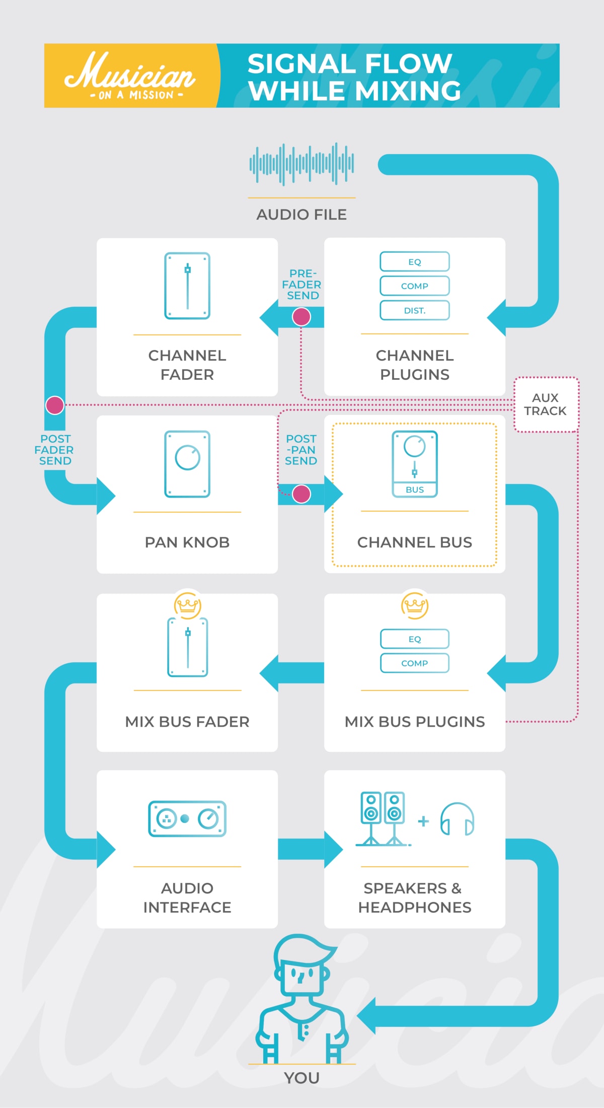
Downloadable Charts to Understand Audio Signal Flow in a DAW Hard drive > insert #1 (compressor plug-in) > insert #2 (EQ plug-in) > fader. Everything else about the basic signal flow remains the same. Two crucially important facts to note about this order: 1. The plug-in processing on the vocal track is not recorded to the vocal audio file, it is only being monitored. 2.

STAGE TUTORIAL Basic Signal Flow Sound System Setup.mp4
AV Inputs & Outputs - Understanding the Flow of Signals ... Understanding the flow of signals within your home theatre starts with becoming familiar with the three distinct types of devices that your home entertainment components fall into: Source Devices, Hub Devices & Sink Devices. Source Devices are easy to identify as they generally only have AV Outputs - they play your media and send the audio and ...
Signal flow for volume/panning in general and for multi ...
From Source to Output: Audio Signal Flow for ... - Videomaker Signal Flow Chart Audio routing is built on a set of stages that follow a sound all the way from its source, input and conversion, channel strip, output stage and ultimately through the speaker and into your ears. Signal Flow - How it works I hope you had a good look at the previous diagram.

The Signal Flow in Ableton Live Incl. Free Wallpaper Download ...
Class C power amplifier circuit diagram and theory. Output ... Inductor L1 and capacitor C1 forms a tank circuit which aids in the extraction of the required signal from the pulsed output of the transistor. Actual job of the active element (transistor) here is to produce a series of current pulses according to the input and make it …

Live Sound Explained: 3. The PA System (Signal Flow Diagram ...
System signal flow diagram [classic] | Creately System signal flow diagram [classic] by André. Edit this Template. Use Creately's easy online diagram editor to edit this diagram, collaborate with others and export results to multiple image formats. You can edit this template and create your own diagram. Creately diagrams can be exported and added to Word, PPT (powerpoint), Excel, Visio or ...
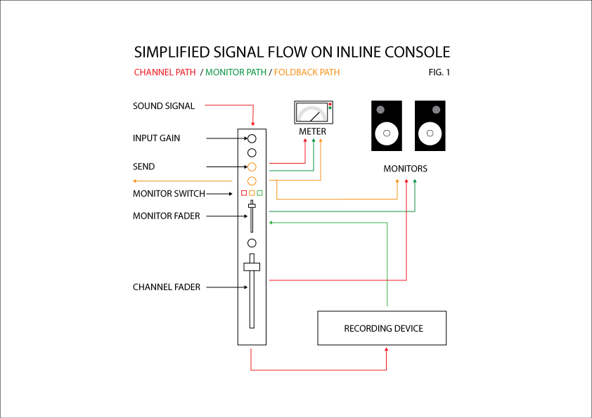
How to Follow Signal Flow on a Large Format Mixing Console ...
Basic CCTV System Diagram. CCTV Network Diagram Example ... ConceptDraw DIAGRAM enhanced with Audio, Video, Media solution is a helpful tool for illustration of a CCTV network. It contains library of vector cliparts of video and TV devices and different digital gadgets for drawing such illustrations Basic Cctv System Diagram
Csound Journal
Understanding Audio Signal Flow in Recording Studio In. Stage 1: Sound Source: Every recording studio's signal flow begins at the sound source. Physical vibrations from an instrument, voice or other source are picked up by a microphone which converts sound energy into electrical energy. A microphone converts sound energy to electricity through a process known as transduction, much the same way ...

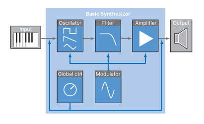
Signal flow chart of the synthesizer for the sound of ...
Mixing: Flow charts and Block diagrams - Lenard Audio Flow charts also show what parts of the mixer can be externally accessed or separated, and which parts are not accessible. (a) Balanced Inputs The example flow chart below, of a single channel shows that the input can be selected for a balanced XLR mic or a line level jack plug. Balanced means that the mic signal is between XLR pins (2 and 3 ...

PreSonus Studio One DAW signal flow diagram. It's important ...
PDF Av Signal Flow Diagram Av Control Diagram av signal flow diagram output to vtc codec output to vtc codec from matrix switcher from matrix switcher stereo dual wall-mounted video input speakers audio output audio output controller tcp/ip lan ctrl tcp/ip lanctrl tcp/ip lanctrl 65" flat panel display video input tcp/ip lanctrl tcp/ip lan scene (source) select audio volume / mute mic on ...

Signal Flow Diagram | Quizlet
Analog Recording Signal Flow (Diagrams + How Does It Work?) The Function Of A Mixing Console. A mixing console allows you to feed your recorded signal into your DAW and then monitor the sound as a full mix via the console faders. Nothing is actually recorded onto the console. After setting your gain levels you will usually find an EQ section on the desk which will allow you to sculpt your sound before ...

Signalfluss in einem Aufnahmestudio
Home Theater Wiring Tips, Diagram & Guide for 5.1-7.1 ... Feb 03, 2015 · Here are some tips on creating professional-worthy audio hookups at home. Wiring Essentials. Surround speaker wires permits acoustic signals to pass from amplifiers to loudspeakers in a standard home theater setup. While this is relatively straightforward, specific properties of the wire in question impact various sound quality factors, such as noise, fidelity …
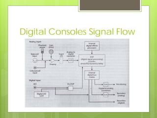
Signal flow and Audio Consoles
PDF MX-1 Audio Signalflow Diagram - Roland Corporation mono channel input 1-4 stereo channel input 5/6 digital channel digital in usb channel usb host 1-4 pc channel analog in pc audio in (from hi-speed usb) pc audio in
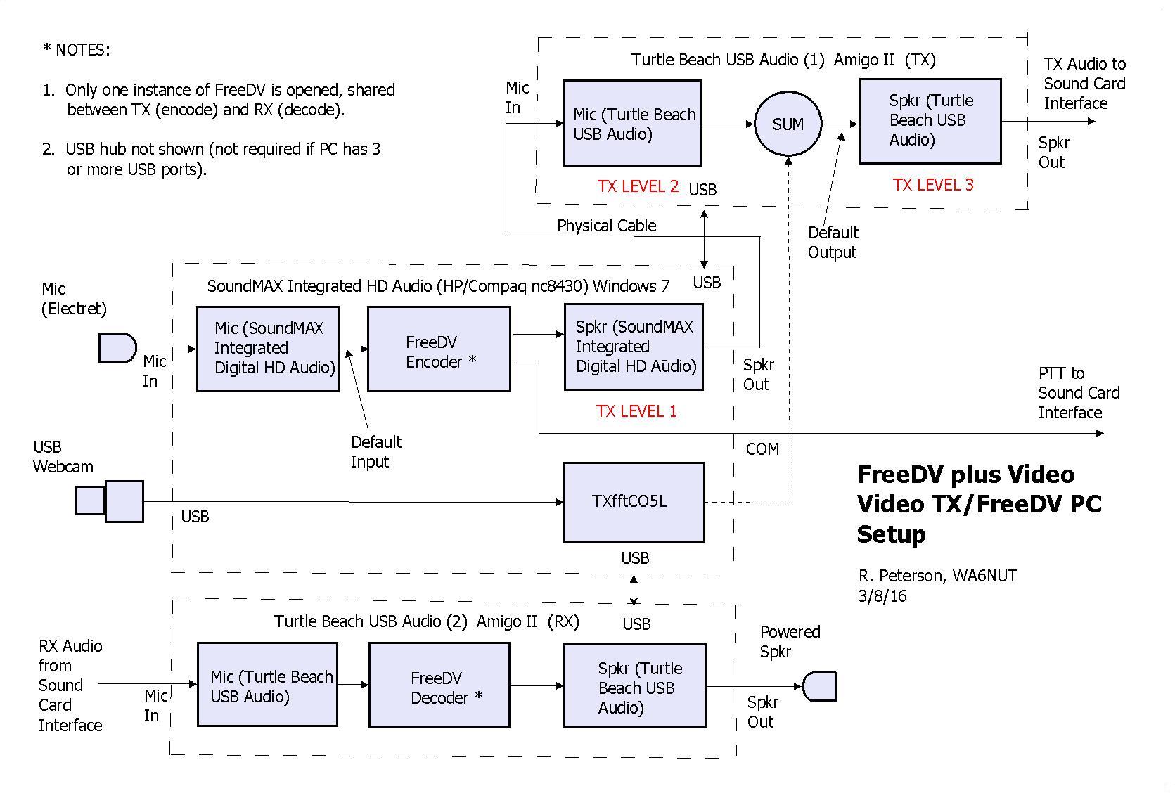
FreeDV plus Video
Quick AV Signal Flow with Lucidchart | DDMC A signal flow diagram shows the signal path (audio, video, network, control, etc.) from inputs to outputs, for the entire AV system. It's essentially a blueprint for the system… and would you buy a house where they didn't have a blueprint?
Church Sound: Signal Flow & Console Operation - ProSoundWeb
Signal Flow - Signature Sound Within our diagram, the microphone (s) take the sound waves from the sound source and convert the sound waves into an electric current (through the process of transduction). Once the audio signal is converted into an electric signal, the electric signal is sent to the console pre amps.

Sub-band coding - Wikiwand
Church Sound: Signal Flow & Console Operation - ProSoundWeb
Live Sound Signal Flow Diagrams | Portfolium
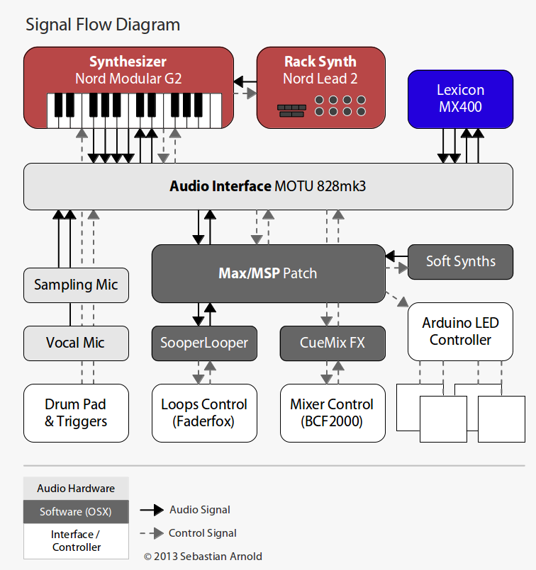
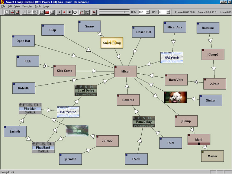
A Portable Digital Mixing Desk with Max/MSP | Sebastian Arnold

Learning all about the Signal Flow life at school and I'm ...
![tb8:surround_configuration [Support]](https://support.dhd.audio/lib/exe/fetch.php?w=593&tok=8b1a20&media=tb8:surround_signalflow_8.zoom62.png)
tb8:surround_configuration [Support]

Audio Signal Flow: What It Is and How to Use It

SKRATCHWORX™ v2 - Sends and Returns
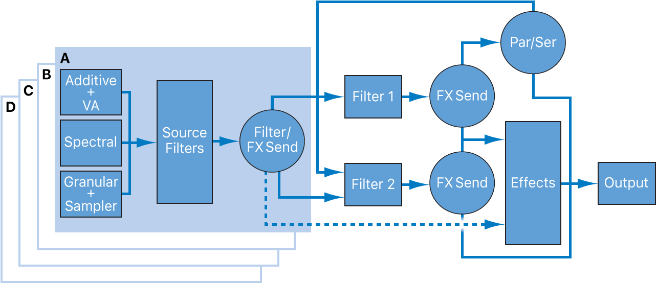
MainStage Alchemy overview - Apple Podrška (HR)
Printable Audio Signal Flow Chart - Cockos Incorporated Forums

Signal Flow - Signature Sound

File:Band Signal Flow Example.png - Wikimedia Commons

Sub-band coding - Wikipedia

Cubase Signal Routing

Setting Up a Simple Home Music Recording Studio - PEDAL POINT ...

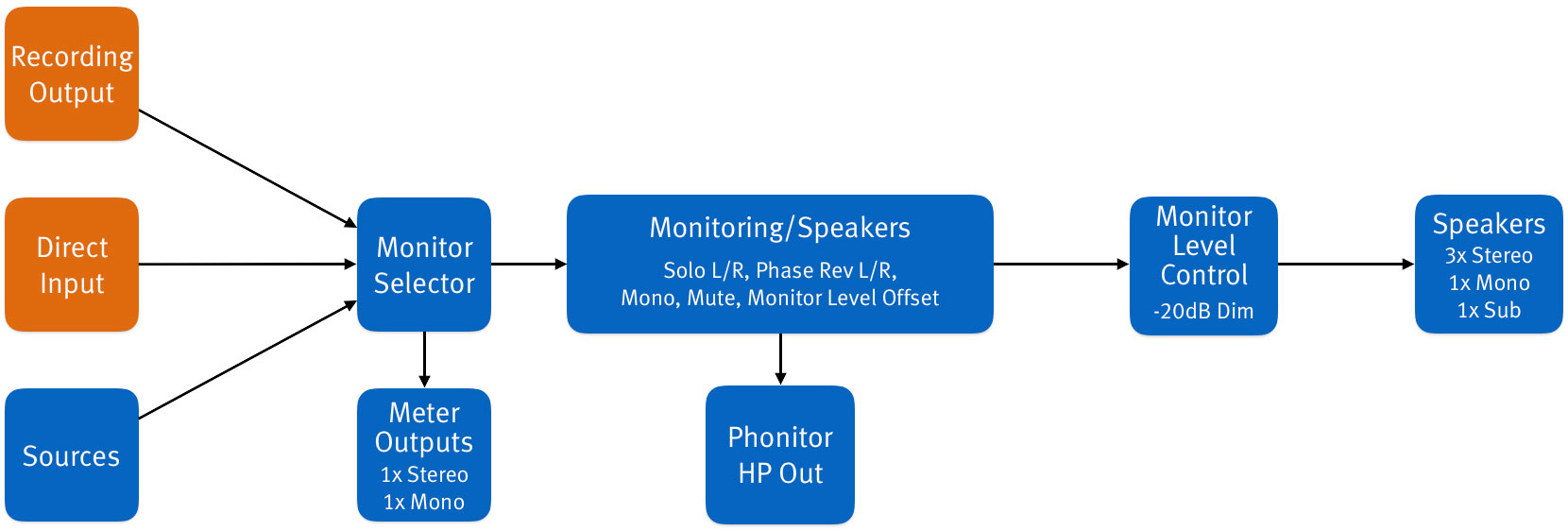
Signal flow of an Audio Monitoring and Authoring Unit system ...
OT: Audio Signal Flow diagram standards?
Audio Signal Flow: What It Is and How to Use It

Analog Recording Signal Flow (Diagrams + How Does It Work ...

Signal Flow - Signature Sound
DMC – SPL

Analog Recording Signal Flow (Diagrams + How Does It Work?)

Digital Guitar Amplifier/Effects Processor - Circuit Cellar
0 Response to "37 audio signal flow diagram"
Post a Comment