36 systems engineering v diagram
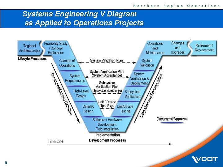
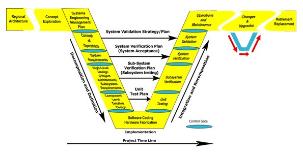
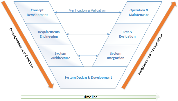
The systems engineering process is often referred to as the ^V diagram (see Exhibit 1050-1). An ITS project begins on the left side of the ^V and progresses down the left side and then up the right side. Then the project is evaluated by validating and verifying the elements on the right side of the ^V with the elements on the left side. Download scientific diagram | Systems Engineering Process (";V" Diagram) from publication: San Diego I-15 Integrated Corridor Management (ICM) System: Phase ...
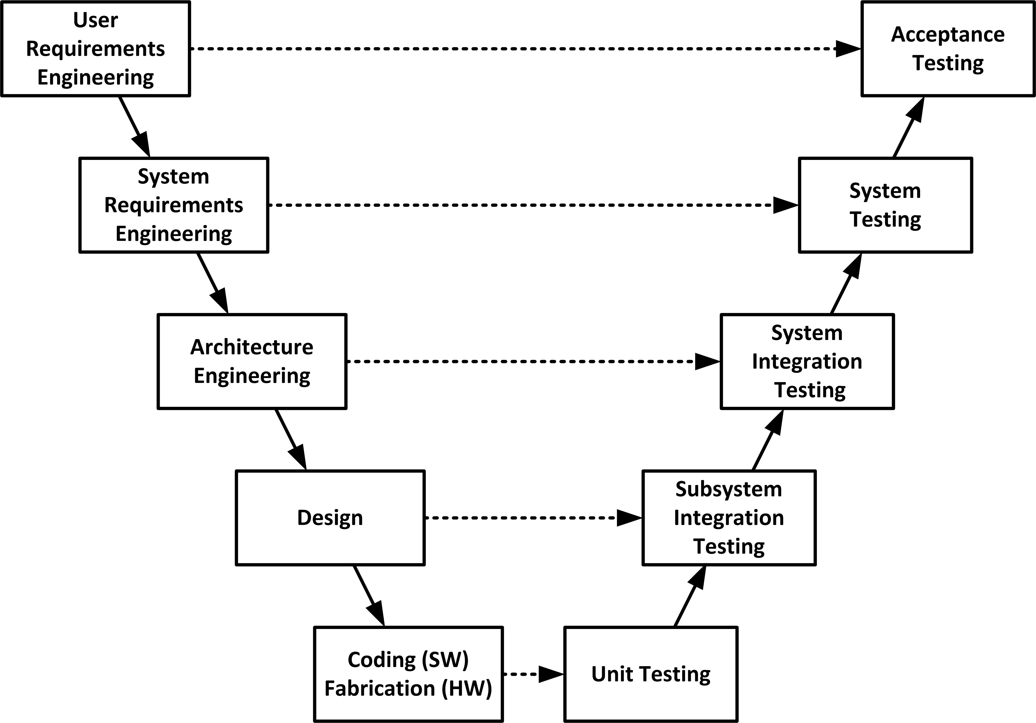
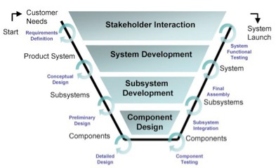
Oct 28, 2019 · What is a V-Diagram? Almost all engineering projects follow a similar trajectory: they start with the definition of high-level customer requirements, and then “waterfall” down through high-level systems engineering, then subsystem development & specification, design, analysis, fabrication, assembly, test, integration, commissioning, and, ultimately, customer delivery and validation.
Systems engineering v diagram
The INCOSE Systems Engineering Handbook 3.2.2 contains a more detailed version of the Vee diagram (2012, Figures 3-4, p. 27) which incorporates life cycle activities into the more generic Vee model. A similar diagram, developed at the U.S. Defense Acquisition University (DAU), can be seen in Figure 3 below. Figure 3. Fig. 2 shows the system engineering V diagram and where to use an iron bird [12]. Iron birds are being used for validation and verification on the system and sub-system level. ... Animated System Engineering Presentation Template. Whether you are a system engineer, an IT Manager or a teacher, you can easily edit the animated slides by labeling the V Model diagram in this PowerPoint presentation template. The template starts off with an introductory slide where you can depict a labeled V Model showing the basic parts of ...
Systems engineering v diagram. Systems Engineering • Development steps • Model-based control engineering • Modeling and simulation • Systems platform: hardware, systems software. EE392m - Spring 2005 Gorinevsky Control Engineering 9-2 ... Control Engineering 9-11 r v F t r r v m pert = = − ⋅ + & & ( ) 3 NASA SYSTEMS ENGINEERING HANDBOOK viii Preface S ince the initial writing of NASA/SP-6105 in 1995 and the following revision (Rev 1) in 2007, systems engineering as a discipline at the National Aeronautics and Space Administration (NASA) has undergone rapid and continued evolution. Changes include using Model-Based Systems Engineering to improve This guide is intended to introduce you to systems engineering and provide a basic understanding of how it can be applied to planning, designing, and implementing intelligent transportation systems (ITS) projects. The guide leads you step by step through the project life cycle and describes the systems engineering approach at each step. Welcome to Systems Engineering! In this student handbook, we would like to explore the subject of systems engineering with you to build a powerful set of concepts with processing tools for your future system design, development, and management projects. Systems engineering is a way of thinking as well as a way of doing. Its roots began with the
The V-Model is a unique, linear development methodology used during a software development life cycle (SDLC).The V-Model focuses on a fairly typical waterfall-esque method that follows strict, step-by-step stages.While initial stages are broad design stages, progress proceeds down through more and more granular stages, leading into implementation and coding, and finally back through all ... Systems engineering is often understaffed, and the continuous nature of the DevSecOps environment puts a strain on available systems engineering resources. Understanding how much work is being expected and its production rate supports maximizing the flow and increasing the value of many systems engineering activities. Staffing practices are a ... Management of the Systems Engineering Process, [Final Draft], 26 September 1994.) In summary, systems engineering is an interdisci-plinary engineering management process that evolves and verifies an integrated, life-cycle bal-anced set of system solutions that satisfy customer needs. Systems Engineering Management Is… Processes and procedures are the heart of current descriptions of Systems Engineering. The “Vee Diagram”, ISO 15288, the INCOSE SE Handbook, and enterprise- ...
Systems engineering (SE) is a methodical and disciplined approach for the specification, design, development, realization, technical management, operations and retirement of a system. As illustrated in Figure 1, a system is an aggregation of system elements and enabling system elements to achieve a given purpose or provide a needed capability. V-Model of Systems Engineering Lifecycle. The model of systems engineering used in this guide is based on the ";V" representation. Note, however, that the system life cycle is rarely, if ever, as linear as this simplified discussion might imply. There are often iterative cycles, skipped phases, overlapping elements, etc. Additionally, important ... Download scientific diagram | Overview of V-model of systems engineering. from publication: Integrating Cognitive Systems Engineering Throughout the Systems ... The Enterprise Systems Engineering focuses on the sequential Vee Model (Figure 1) as the primary example of pre-specified and sequential processes. In this discussion, it is important to note that the sequential Vee model and all other variations of the Vee model address the same basic set of systems engineering (SE) activities.
V-MODELS FOR INTERDISCIPLINARY SYSTEMS ENGINEERING
2. Our definition of Systems Engineering. 3. Case Study: Systems Engineering for Modern Buildings. 4. Systems Engineering in Mainstream US Industry. 5. End-to-end Lifecycle Development. 6. Models of Systems Engineering Development (e.g., Waterfall, Spiral). 7. Economics of development. - p. 3/33

System Life Cycle Process Models: Vee - SEBoK
The V diagram is a useful representation of Systems Engineering, but it does have drawbacks in that it hides several key aspects. Firstly, iteration. The ability to iterate is essential to good Systems Engineering because the details of the higher levels are dependent on the design of the lower levels. Secondly, Lifecycle view.
Approaches for Integrating Systems Engineering into Your Agencys
The “V” Systems Engineering Model Many different process models have been developed over the years that specify a series of steps that make up the systems engineering approach 6. Among these models, the “V” model, shown in Figure 7, is merging as the de facto standard way to represent systems engineering for ITS projects. Don’t be

V-Model - Wikipedia
Its overall trajectory is often represented by the ";V" diagram: The left side of the diagram focuses on the definition and decomposition of the system to be built, the base on the building of the system components, and the right side on the integration and testing of system components, as well as acceptance and operation of the system.

Systems Engineering Programme | RNO/ITS - PIARC (World Road ...
The Connected Corridors project generally followed the V diagram of the systems engineering cycle as illustrated in the Federal Highway Administration's Systems Engineering Guidebook: In this framework, stakeholder involvement is: Very high early in the project during concept exploration and system planning.

Verification and Validation | The MITRE Corporation
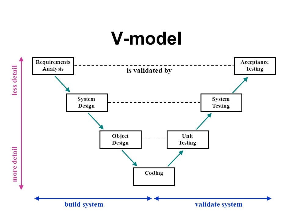
The V-model of the systems engineering process. The V-model is a graphical representation of a systems development lifecycle. It is used to produce rigorous development lifecycle models and project management models. The V-model falls into three broad categories, the German V-Modell, a general testing model and the US government standard.

Systems Engineering and Stakeholder Engagement | Connected ...
"System engineering is a robust approach to the design, creation, and operation of systems. In simple terms, the approach consists of identification and quantification of system goals, creation of alternative system design concepts, performance of design trades, selection and
Running head: Extending the System Engineering “V†Extending ...
DAU SYSTEMS ENGINEERING BRAINBOOK. About. This guide is organized according to the eight technical processes and eight technical management processes which make up the systems engineering process. These 16 processes together provide a structured approach to increasing the technical maturity of a system and increasing the likelihood that the ...
Diagram Systems Engineering V-Model PNG, Clipart, Agile ...
The ";V" diagram is similarly punctuated by a series of major milestones (labeled Document/Approval in the figure) where the output of the previous step is ...
Using V Models for Testing
Download scientific diagram | the V diagram in systems engineering. from publication: Generative Model for Conceptual Design of Defence Equipment ...
1. Executive Summary
• "Systems Engineering (SE) is a disciplined approach for the definition, implementation, integration and operations of a system (product or service) with the emphasis on the satisfaction of stakeholder functional, physical and operational performance requirements in the intended use environments over its planned life cycle within cost and schedule constraints. Systems Engineering includes the engineering activities and
ICMS Concept of Operations for a Generic Corridor - ITS Report
• Model-based Systems Engineering provides a mechanisms for driving more systems engineering depth without increasing costs • Data-centric specifications enable automation and optimization, allowing SEs to focus on value added tasks and ensure a balanced approach is taken • Unprecedented levels of systems understanding can be achieved through

Systems Engineering Process ("V" Diagram) | Download ...
SMC Systems Engineering v Integrated Master Plan (IMP) Narrative/Systems Engineering Management Plan (SEMP) ... Sample functional flow diagram– showing interrelation of various levels..... 207 Figure 46. Timeline sheets–show sequence of operational and concurrent action ..... 208 Figure 47. Reliability functions calculated for each major ...
System Engineering Development Style | by David Chew Vee Kuan ...
Tim Weilkiens, in Systems Engineering with SysML/UML, 2007. 1.4.10 V-Model XT. The V-Model is an approach model that was developed by commissioning of the State of Germany for planning and implementing system development projects. It considers the entire lifecycle of a system nicely fitting the line of thinking in systems engineering. The current V-Model XT from 2004 is based on V-Model 97 ...

System Life Cycle Process Models: Vee - SEBoK
Systems Engineering practices rely on a variety of documents and diagrams to describe interface specifications and instances of interaction. The SysML[1] specification provides a precise model based representation for interfaces and interface instance integration. This paper will describe interface engineering
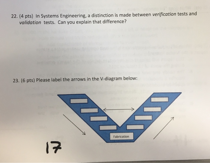
Solved 22. (4 pts) In Systems Engineering, a distinction is ...
Animated System Engineering Presentation Template. Whether you are a system engineer, an IT Manager or a teacher, you can easily edit the animated slides by labeling the V Model diagram in this PowerPoint presentation template. The template starts off with an introductory slide where you can depict a labeled V Model showing the basic parts of ...
Systems Engineering Guide: System Life Cycle Process Models ...
Fig. 2 shows the system engineering V diagram and where to use an iron bird [12]. Iron birds are being used for validation and verification on the system and sub-system level. ...
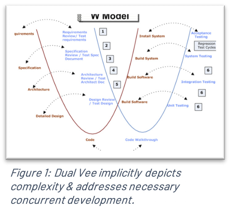
Agile in Systems Engineering: The New Dual V | Cprime
The INCOSE Systems Engineering Handbook 3.2.2 contains a more detailed version of the Vee diagram (2012, Figures 3-4, p. 27) which incorporates life cycle activities into the more generic Vee model. A similar diagram, developed at the U.S. Defense Acquisition University (DAU), can be seen in Figure 3 below. Figure 3.
System Safety in Systems Engineering Process
Systems Engineering Jr. Handbook

Systems Engineering - Letra Engineering ltd
V-MODELS FOR INTERDISCIPLINARY SYSTEMS ENGINEERING
Chapter 2

Figure 4 from System of Systems Engineering and Family of ...
Systems Engineering on AVP - AVP

Fundamentals of Systems Engineering | Aeronautics and ...

Open System Engineering Environment | The Eclipse Foundation

CAV Safety Hub: Why lidar technology is the way forward

Topics | Systems Engineering Process | Loughborough University

SYSTEM ARCHITECTURE: The Crucial Step Between Initial and ...

MBSE: Aligning Systems Engineering with Verification and ...

Diagram Systems engineering V-Model, ppt template figure ...
Systems Thinking in the MEM Program | Inside Our Program ...

System Engineering - GESTE Engineering SA
V-Model Systems Engineering Systems Development Life Cycle ...

Systems Engineering and the Project Delivery Process in the ...
0 Response to "36 systems engineering v diagram"
Post a Comment