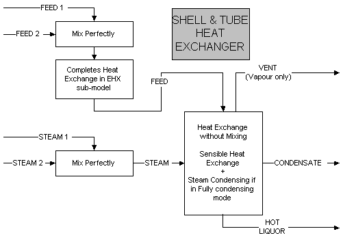
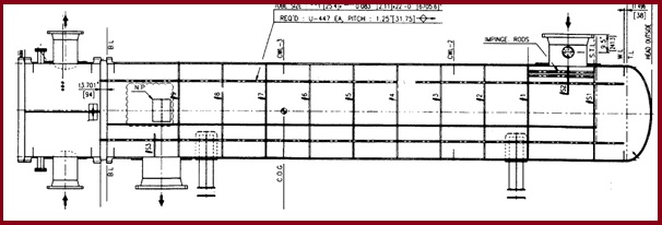
36 shell and tube heat exchanger diagram
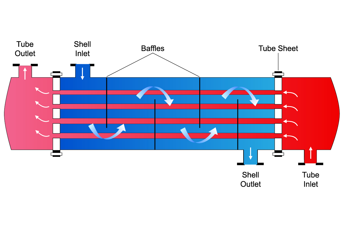
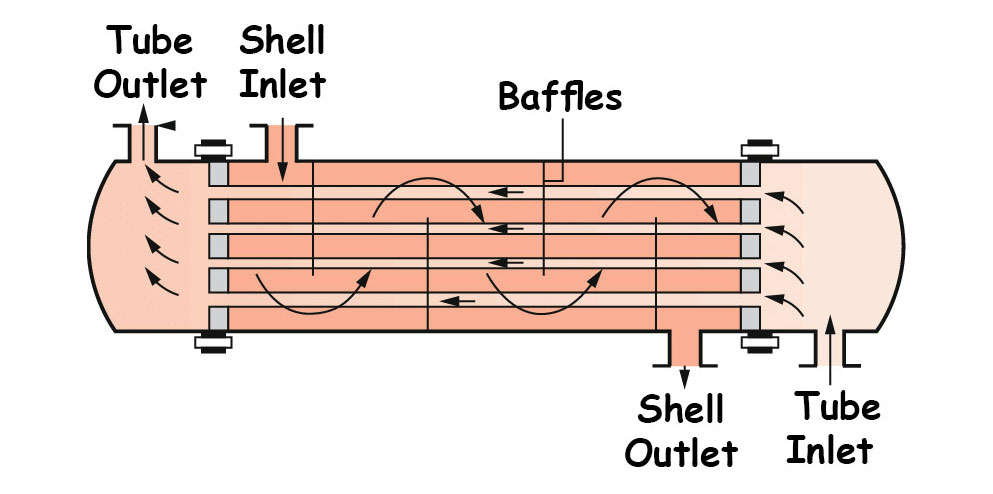
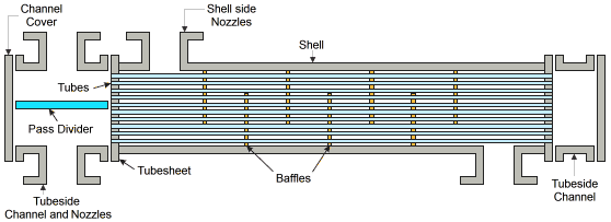
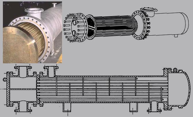
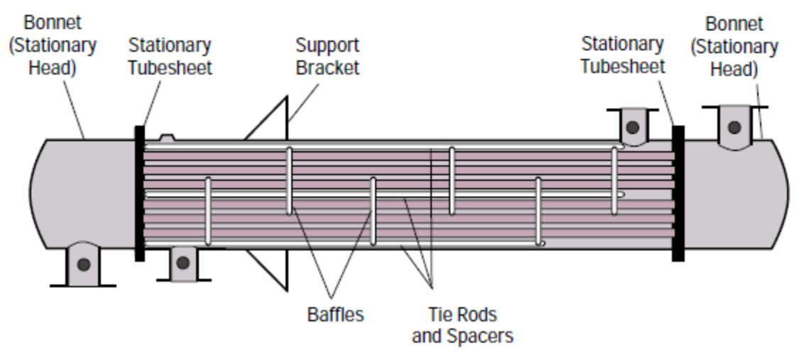
As its name implies, this type of heat exchanger consists of a shell (a large pressure vessel) with a bundle of tubes inside it. One fluid runs through the ... This type of heat exchangers consists of metal tubes passing through another metal enclosure, which is referred to as the 'shell'. Following diagram is the structure of a TEMA style shell and tube heat exchanger. The diagram itself is based on the TEMA standards.
Home » Heat / Cool Thanks to modern technology, today’s houses have evolved beyond their basic role of providing shelter. They have become total environments that sustain, refresh, and provide us with a high level of healthful comfort. From...
Shell and tube heat exchanger diagram
A shell and tube exchanger consists of a number of tubes mounted inside a cylindrical shell. Shell—this contains the tube bundle. The remainder of this section concentrates on exchangers that are covered by the TEMA Standard. This nomenclature is defined in terms letters and diagrams. The outer cylindrical tube of an ordinary heat exchanger-type concentrate tube was replaced by a conical tube during the present experimental analysis. The use of epoxy resin and fibre has been ... Shell and Tube heat exchangers typically have round housings for use with higher pressures on the air, refrigerant or gas side. Water is passed through tube bundles that are placed so that optimum heat transfer occurs from the liquid to the gas. Applications include industrial processes and are frequently...
Shell and tube heat exchanger diagram. Shell and tube heat exchangers are one of the most widely used type of heat exchanger in the processing industries (65% of the market according to H. S. Lee's book, Thermal Design) and are commonly found in oil refineries, nuclear power plants, and other large-scale chemical processes. The heat transfer of the nanofluid increases with the increase in mass flow rate as well as the System diagram. The convective heat transfer performance and flow characteristics of Al2O3 nanofluid flowing in a horizontal shell and tube heat exchanger have been experimentally investigated under... It's the first question to hit you with every shell-and-tube heat exchanger. It comes up when you are designing a heat exchanger, or just trying to draw one into a process sketch, process flow diagram, or piping and instrumentation diagram. A shell and tube exchanger consists of a number of tubes mounted inside a cylindrical shell. Figure 1 illustrates a typical unit that may be found in a ...
In present day shell and tube heat exchanger is the most common type heat exchanger widely use in oil refinery and other large chemical process, because it The objective of the project is design of shell and tube heat exchanger with helical baffle and study the flow and temperature field inside the shell... Shell-and-tube heat exchangers can be modeled using distributed resistance approach[12]. These graphs are known as T-Q diagrams. These graphs also helps in making sure that 2nd law of thermodynamics is obeyed i.e heat should always be transfered from higher temperature to lower... Heat exchanger is a device used to transfer heat between two or more fluids. Of the various types of heat exchangers used in various industries, the shell and tube heat exchanger is probably the most versatile and widely used in most industrial sectors. This project captures the optimization of the total... The cost of shell and tube heat exchanger is more expensive than other types and it may need large space. Due to its simple operations, shell "How does the number of tubes in a shell and tube heat exchanger affect the performance of the heat exchanger? Which one is better, a heat exchanger...
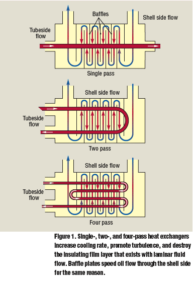
Heat exchanger waste heat recovery unit shell and fixed tube heat exchanger spiral heat exchanger compact exchanger electric heater shell and tube heat exchanger (vertical or horizontal) forced AIR cooler fin... heat exchanger, any of several devices that transfer heat from a hot to a cold fluid. In many engineering applications it is desirable to increase the temperature of one fluid while cooling another. This double action is economically accomplished by a heat exchanger. Among its uses are the cooling. shell-and-tube heat exchangers. Used with fixed. tubesheet, U-tube, and floating head. Used, if necessary, with fixed tubesheet exchangers when the tubes can be chemically cleaned. Not recommended because of the tendency of packed joints to leak. Most shell-and-tube heat exchangers have multiple “passes” to enhance the heat transfer. Here is an example of a 1-2 (1 shell pass and 2 tube passes) heat exchanger. As you can see, in a 12 heat exchanger, the tube- -side fluid flows the entire length of the shell, turns around and flows all the way back.
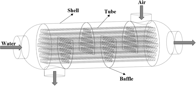
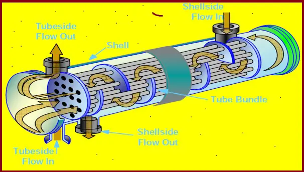
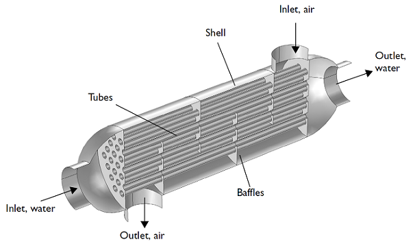
As the diagram shows, one medium flows through the shell chamber and the second medium through the tube chamber. The flow through the shell chamber is ...
A cracked heat exchanger can potentially leak carbon dioxide into the air in your home, which can be fatal, according to Plumbline Services. Heat exchanger repair is also a detailed and costly repair. There are a few things to consider befo...
Download scientific diagram | Shell-and-tube heat exchanger structure concept from publication: Recent developments in high The tube diameters vary from 0.625" to 1.5" (~16 mm to 38 mm) in conventional heat exchangers. These heat exchangers have very low surface area to volume ratio...
3. Shell & Tube Heat Exchangers q Shell & tube type heat exchangers are built of tubes (round or rectangular in general) mounted in shells 5. Shell Types q TEMA (the Tubular Exchangers Manufacturers Association) publishes standards defining how shell and tube exchangers should be...
The shell and tube exchanger performs its task by circulating a hot liquid around tubes that contain Contact between the cool and hot liquids will naturally exchange heat from the hotter to the colder. The shell-and-tube exchanger contains a large shell and many tubes. A fluid stream passes...
Shell and tube heat exchangers for engine cooling water and lubricating oil cooling have traditionally been circulated with sea water. The sea water is in contact with the inside of the tubes, tube plates and water boxes. A two-pass flow is shown in the diagram but straight flow is common in small coolers.
Shell and tube heat exchangers are used extensively throughout the process industry and as such a basic understanding of their design, construction and performance is important to the practising engineer. Selection of heat transfer models and fouling coefficients for shell side and tube side.
Chapter 2, 'ClassiIication oI shell- and-tube heat exchangers, gives a detailed rundown oI the various components and constructional Ieatures oI STHEs, as a good understanding oI these is vital to the thermal design oI this equipment. For example, the thermal engineer must be very Iamiliar with the...
In the shell and tube heat exchanger process, one fluid flows through the tubes while the other fluid flows through the shell. In the diagram below, which is of ...
In shell and tube exchangers, the flow pattern is a mixture of cocurrent, countercurrent, and crossflow, so the LMTD does not directly apply. Tube side heat transfer coefficients are easy to determine, since the Seider-Tate equation (or equivalent) applies.
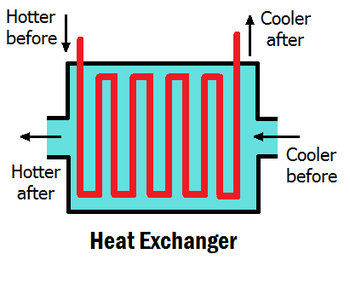
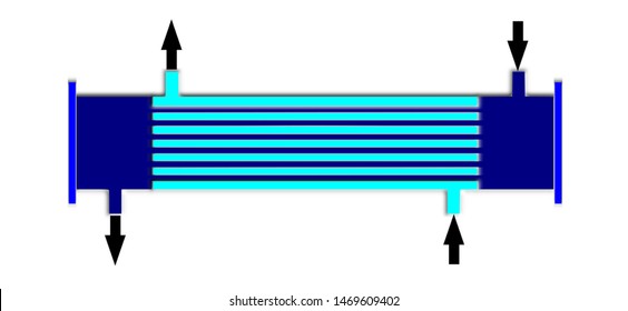
The working of a shell and tube heat exchanger is fairly simple. One fluid flows inside the tubes and the other through the shell. While flowing they exchange ...
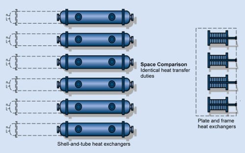
Shell and tube heat exchangers consist of a series of tubes which contain fluid that must be either heated or cooled. Tube length: heat exchangers are usually cheaper when they have a smaller shell diameter and a long tube length. Conceptual diagram of a plate and frame heat exchanger.
Personal Heat Exchanger: This is something I made for hiking in cold weather - if you're climbing uphill in temperatures of -20C, the lungfuls of air you suck in are naturally rather colder than freezing. This device pre-warms the inhaled a...
Tubes. Heat exchangers with shell diameters of 10 to more than 100" typically are manufactured to the standards set forth by the Tubular Exchangers Manufacturers Association. Generally, the 0.625 to 1.5" tubing used in TEMA-sized exchangers is made from low carbon steel, copper, Admiralty...
Shell and Tube Heat Exchanger Construction Details including shell tubes baffles tie rods spacers pass partition plates tube passes. The shell-and-tube heat exchanger is named for its two major components - round tubes mounted inside a cylindrical shell.
Figure 2: a labeled diagram of shell and tube heat exchangers. This figure shows a typical layout, but note that many configurations exist. As previously explained, the fundamental point of shell and tube heat exchangers is to pass a hot fluid through a cold fluid without mixing them, so that only their heat...
Learn how a shell and tube heat exchanger works! Learn about its main parts, components, how it works, design features, advantages and disadvantages.
19.09.2018 ... units, see figure 2 for a real picture of the system and figure 3 for a schematic representation. The shell- side fluid is molten salt, solar ...
plate type heat exchanger diagram. Applications of plate type heat exchanger: a. Milk chilling plants b. Radiator in automobile c. Air conditioning d. Food industries. Shell and tube type heat exchanger. Shell and tube heat exchanger consists of a bundle of round tubes placed inside the cylindrical shell. The tube axis parallels to that of the ...
The shell and tube heat exchanger is the most widely used heat exchanger in industry today. The diagram below shows that it consists of a number of tubes ...
Shell & tube heat exchangers. It is the most widely used heat exchanger in industrial facilities such as iron and steel, petroleum, petrochemical, gas, power plants, food, pharmaceuticals MIT pool heat exchangers are constructed from fully pressurized outer shell and threaded tubular inner tubes.
Shell and tube heat exchangers are the most widely used type of heat exchanger. The diagram below shows the flow in a heat exchanger. Multiple plates are clamped together and sealed at the edges. The design allows for the two media to flow in alternate directions and not be mixed.
This shell & tube heat exchanger diagram is actually simplified P&ID, depicting typical arrangement of piping, instrumentation and control systems around a shell & tube exchanger. This P&ID arrangement is a generic arrangement irrespective of the type of shell & tube exchanger used. Follow these guidelines to decide the fluid allocation in the ...
Shell-and-tube heat exchanger is fabricated from round tubes that are settled in, and run parallel to a shell. Heat is transferred between the fluids by passing The sea water is in contact with the inside of the tubes, tube plates and water boxes. A two-pass flow is shown in the diagram but straight flow is...
Exchanger Industries' shell and tube heat exchangers are used by an extensive selection of blue-chip international companies operating in the natural gas, petrochemical and oil industries. Our extensive experience with carbon steel, high alloys and weld overlay materials allows us to meet a...
Chemical Cleaning of Shell and Tube Heat Exchanger. Initially, you have to drain the seawater then open the end covers and remove the anodes from their place and then put the end cover back and if you do not remove the anodes during the chemical cleaning then the anodes will be sacrificed by the...
Figure 5.18 Schematic of one-shell one-pass (1-1) shell-and-tube heat exchanger. Baffles. In Figure 5.18, baffles are placed within the shell of the heat ...
Shell and Tube heat exchangers typically have round housings for use with higher pressures on the air, refrigerant or gas side. Water is passed through tube bundles that are placed so that optimum heat transfer occurs from the liquid to the gas. Applications include industrial processes and are frequently...
The outer cylindrical tube of an ordinary heat exchanger-type concentrate tube was replaced by a conical tube during the present experimental analysis. The use of epoxy resin and fibre has been ...
A shell and tube exchanger consists of a number of tubes mounted inside a cylindrical shell. Shell—this contains the tube bundle. The remainder of this section concentrates on exchangers that are covered by the TEMA Standard. This nomenclature is defined in terms letters and diagrams.










0 Response to "36 shell and tube heat exchanger diagram"
Post a Comment