37 hydraulic spool valve diagram
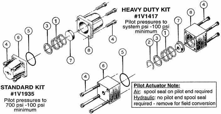
20-50-K4 08650015 V20 D/A Motor Spool. FOR SINGLE ACTING FLOAT USE 20-50-03 AND K-20-R. V20 SPOOL ACTION KITS. K-20-D 08650105 V20 Detent Kit (3 Position) K-20-R 08650106 V20 Spool In Detent (S/A Float) K-20-PA1 08650630 Air Shift. K-20-VH-B 08650151 Handle Kit Complete. V20 NPT Pipe Thread. 22 How Do I Hook Up A Hydraulic Valve? To extend cylinder, pull handle away from valve. When handle is released, the valve spring centers to neutral stopping cylinder. Neutral: Oil circulates from the pump through the valve and back to the reservoir. Work ports are blocked. To retract cylinder, push handle toward valve.
procedure to assure the valve spool does not lock or bind as a result of the tightening. IF THE VALVE SPOOL BINDS IN ANY WAY OR REFUSES TO RETURN TO NEUTRAL WITH THE SPRING WHEN THE LEVER IS RELEASED, DISCONTINUE USE AND CALL FACTORY. 4. Since the kick-out operates from hydraulic pressure, the valve may not kick out when the oil is cold.

Hydraulic spool valve diagram
ROTARY SPOOL VALVES Rotary spool valves also use a spool fitted in a sleeve but in this case the spool is rotated to select the flow paths rather than sliding (figure 7). the cylinder is subjected to a negative ('runaway') load, or decelerating a high inertia load. A valve may therefore have to be selected with a pressure rating higher than the The phantom leak is fixed! Finally!Thank you to Jake Zeigler and CE Smith for the helpProduced with CyberLink PowerDirector 12 HYDRAULIC PUMPS 6-9 HYDRAULIC VALVES HYDRAULIC HOSES HYDRAULIC FITTINGS 3 4 5 HYDRAULIC RESERVOIR TANKS 10 POWER TAKE OFF (PTO) 11-12 WET KIT SYSTEMS 13-16 WET KIT ( DUMP TRAILER) QUOTE / ORDER SHEET 17. 8-5-265 Super Dump 73-40-110 SAT Hoist 7-3-120 SAT Hoist Hydraulic Operated Tailgate Lift Cylinder
Hydraulic spool valve diagram. Each square section in a directional control valve schematic symbol — called an envelope — represents a position that the valve spool can be in. The arrangement of symbols and arrows inside each envelope tells you how the ports are interconnected when the valve is in that position. Let's look at each of the 3 positions in this valve, in ... Hydraulic directional spool valve is a relative motion between the valve spool and valve housing, used for controlling fluid-flow direction of actuator motion (movement), select alternative hydraulic oil control circuits, achieve logic control function. The hydraulic spool valves target is to reach different mechanical movement of actuator ... Check circulation/filter pump for problems. Hydraulic unit temperature high. Check cooling pump operation. Check the cooler water strainer. Check water thermostat operation. Check that none of the pressure relief valves were set too low. If required, correct the setting. Return filter blocked. Replace old filter with new filter insert. return hydraulic boost passageways ensure reliable shifting . A four-land design provides smooth, balanced spool movement . 10000 psi HP Series Spool Valves Simple sliding-spool valves eliminate complex valve circuits for four-way control in high pressure systems . A full range of actuators, spools and electrical options are available .
They're simple, compact and heavy duty designed, with cast iron body and steel spool. Available from 2--way to 10--way, diverter valves are suitable to intercept and divert the flow on hydraulic systems, wherever movement sequence or control selection of different actuators is needed. Diverter valves DGR002A 3 valve. Pump 2 is in contact with the dumping valve spool through the "open centre" of the steering valve spool, but when the steering spool is drawn from its neutral position BV2 prevents the oil flow from pump 2 from going to the dumping function. In this way the steering is prioritised. All oil from pump 2 then goes to the steering. Sep 18, 2018 · This valve below has a solenoid on one end and a spring on the opposite end. Now we are going to insert the spool into the body. This is an Eaton-Vickers #2 Spool. By combining the two Pictures, we get a full valve operation. Combined valve operation. Shown here, the valve is in its non-energized position. The Spring is in control. Simple, compact and heavy duty designed monoblock valves from 1 to 6 sections for open and closed centre hydraulic systems. H Fitted with a main pressure relief valve and a load check valve. H Available with parallel or series circuit. H Optional carry--over port (only for parallel circuit). H Diameter 20 mm --0.79 in interchangeable spools.
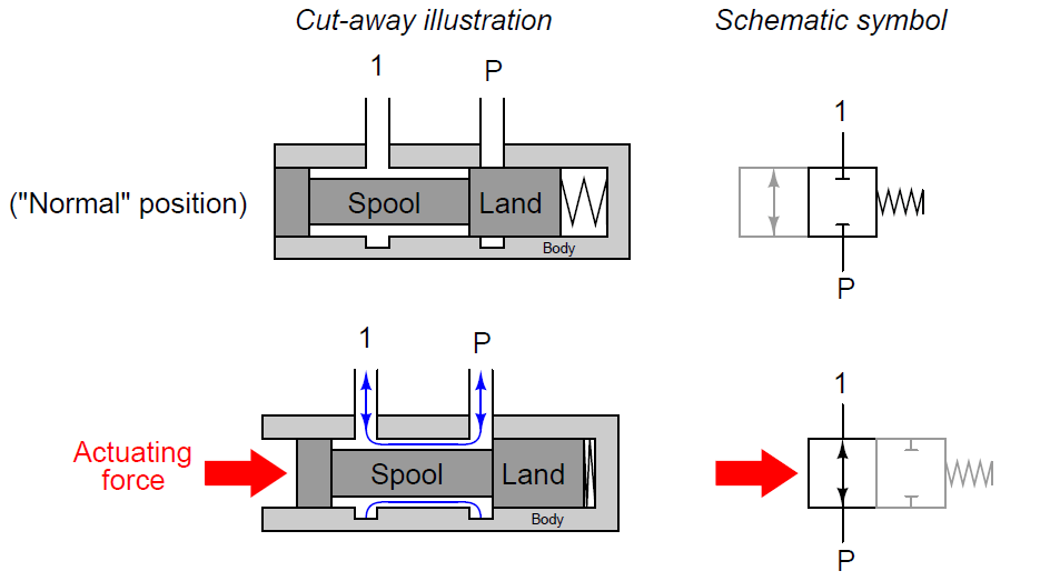
spool valveA spool valve is a multidirectional hydraulic or pneumatic valve usually operated by a joystick. It has several hoses attached to it leading to different pneumatic rams. The detent function of the valve doesn't work Hydraulic hoses are hooked up incorrectly. Find the diagram of the detent valve set up. There will be input valves for the pressurized and un-pressurized hose connections, and the diagram will show you which ones go on which side of the detent valve and in what order. Check for leaks. The bottom symbol shows a three-way three position valve that is hydraulically operated. This valve also has two end springs to return the spool to the centre position when no pilot signal is available. Note how the hydraulic pilot is shown as a solid triangle although if this was a pneumatic pilot it would be shown as a clear triangle. Oct 14, 2019 · When we see a spool valve schematic, we can see it is made up of boxes, each containing a number of lines and arrows. The number of boxes that make up a valve symbol indicates the number of possible positions the valve has. Flow direction is indicated by the arrows in each box. These arrows represent the flow path the valve provides when it is ...
Monoblock Hydraulic Directional Control Valve, 3 Spool, w ...
relief valve (e.g.3rp...) open centre valve (cc.2vdf...) relief valve / lowering valve (e.g. 2mb...) normally open solenoid check valve (e.g. 9526) normally closed solenoid check valve solenoid operated 6 port diverterichageover valve m9278) solenoid diverter valve with al drain (eg.m9848...) direct aci'ing solenoid directional valve (spool form 1
Henderson Executive Airport
Spool valves are usually referred to by the nomenclature 3/2 or 5/3 etc., where the first number relates to the number of ports and the second to the number of different spool positions. We hope you enjoyed this short introduction to pneumatic and hydraulic spool valves.

Hydraulic Spool Valve Diagram | Valve Spool Function - Finotek
Hydraulic Kick-out Adjustment - The SH & SHA models have an adjustable single hydraulic kick out preset to 800-1000 psi. The HHA model comes equipped with a double hydraulic kick out preset to 800-1000 psi. To adjust kick-out pressure: Locate jam nut, and set screw on the spool action cap. (Opposite valve's handle)

Schematic of an electro-hydraulic servo-valve with flapper ...
by a sliding spool valve which can be actuated a hand or foot operated lever or an electric solenoid. The image to the right shows a cutaway of an actual hydraulic control valve. The valve shown in the illustration is a open center valve, meaning that the oil flow is returned to the reservoir when the valve is in the neutral position.

Hydraulic Spool Valve Diagram | Hydraulic Valves Spool Diagram
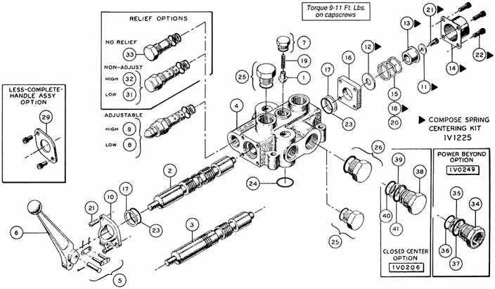
Open center or through center valves need to be connected in series using power beyond porting. Power Beyond allows unused flow to power multiple valve sets downstream. Power beyond also allows the designer to choose which valve sections are more important than another. In a hydraulic system, there can be multiple operator locations.
How a hydraulic self-leveling valve works | Lefebure
VES Valves PARALLEL HYDRAULIC CIRCUITS OUTLET CONVERSION PORT OPTIONS The most common type of hydraulic circuit is the par-allel circuit. Refer to the parallel circuit diagram. With all valve spools centered, the pump flow will return to tank at low pressure through the open center bypass. When a spool is actuated, the open center bypass is
Model BA - 1 Spool Parts | Cross Mfg.
Winch. The diagram shows a winch powered by a hydraulic motor. The directional control valve with built-in relief features optional flow control to control the speed of the winch . The hydraulic pump and motor must be matched to the torque requirements of the winch.
Rotary valve spool/sleeve assembly. The spool rotates and ...
H A wide range of fixed setting antishock+anticavitation port valves. H Intermediate sections for several types of circuit. H Available manual, pneumatic, hydraulic and ON/OFF and proportional electro--hydraulic spool control kits. H Diameter 14 mm (0.55 in)interchangeable spools. 3rd edition August 2005: This edition supercedes all prior ...
Applied Sciences | Free Full-Text | Energy Regeneration ...
Valves Proportional Valves Coils & Electronics Bodies & Cavities Technical Data SH CV LM FC PC LE DC MV SV PV CE BC TD Spool Type, 3-Way Valve Series DSL083 SV61 Flow (Q) 8 2 4 1 LPM GPM 0 11 3 15 4 Hydraulic Oil 150 SSU @ 100°F (32 cSt) r) 0 20 40 100 7 6 4 1 3 80 PSI Bar 60 Pressure Drop vs. Flow(Through cartridge only) DSL083A 2 Flow (Q) 8 ...

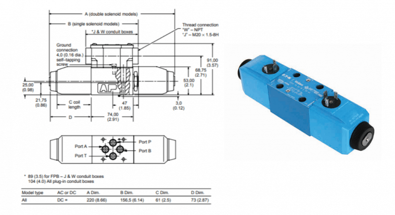
What is a 4-way Solenoid Valve ? | Instrumentation Tools
Because the valve core and valve sleeve have a lubricating film of hydraulic oil, the friction factor is very small, and the spool mass is very small (2.547g), therefore, positive pressure between the spool valve and valve sleeve caused by the two accelerations is also very small; friction resistance change caused by it can be neglected, and ...

Solenoid Hydraulic Pump Motor Wiring Diagram - Complete ...
About Press Copyright Contact us Creators Advertise Developers Terms Privacy Policy & Safety How YouTube works Test new features Press Copyright Contact us Creators ...
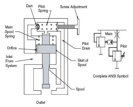
Pressure Control Valves: Hydraulic Pilot Operated Relief ...
HYDRAULIC PUMPS 6-9 HYDRAULIC VALVES HYDRAULIC HOSES HYDRAULIC FITTINGS 3 4 5 HYDRAULIC RESERVOIR TANKS 10 POWER TAKE OFF (PTO) 11-12 WET KIT SYSTEMS 13-16 WET KIT ( DUMP TRAILER) QUOTE / ORDER SHEET 17. 8-5-265 Super Dump 73-40-110 SAT Hoist 7-3-120 SAT Hoist Hydraulic Operated Tailgate Lift Cylinder

2 Spool 8 GPM Prince MB21GB5C1 DA Valve w/Float ...
The phantom leak is fixed! Finally!Thank you to Jake Zeigler and CE Smith for the helpProduced with CyberLink PowerDirector 12

Hydraulic Pilot-Operated Valves | Hydraulic Valve
ROTARY SPOOL VALVES Rotary spool valves also use a spool fitted in a sleeve but in this case the spool is rotated to select the flow paths rather than sliding (figure 7). the cylinder is subjected to a negative ('runaway') load, or decelerating a high inertia load. A valve may therefore have to be selected with a pressure rating higher than the
Free body diagram the solenoid valve spool mechanism ...
Medical diagram

Animation - How hydraulic ram and valve block spool works ...

Lego Hydraulics - Page 4 - LEGO Technic, Mindstorms ...

ELECTRO SECTION FOR MB3 HYDRAULIC SPOOL VALVE (YLMB34621)

Hydraulic Monoblock Spool Valve for Massey Ferguson ...
Cross Hydraulic Valve Diagram - Wiring Diagram

Tilt Valve Spool

Bearing surface area of valve spool | Download Scientific ...

Toro Professional 22973G, TRX-20 Trencher, 2016 (SN ...
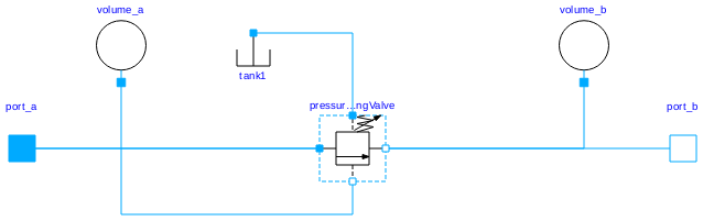
Hydraulic: Valves.PressureControl.SequenceValve ...

Forces acting on the valve spool. | Download Scientific ...
Eames Chair Diagram Schematics - 1951 Chair Poster Hanging on Wall

Prince Single Spool Monoblock Hydraulic Valve - 8 GPM ...
25 Cross Hydraulic Valve Parts Diagram - Wiring Database 2020

Experimental setup: rigid cylindrical chamber, (A ...
Fluid Power Systems | Hydraulic System Working ...

Closeup of skeleton hand model

Spool Valves - YouTube

Cross Hydraulic Valve Diagram - General Wiring Diagram

Principal structure of hydraulic cylinder controlled by ...

Pancakes, Eggs, and Bacon
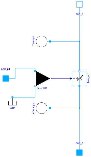
Hydraulic: Valves.DirectionalControl.HydraulicActuation ...
0 Response to "37 hydraulic spool valve diagram"
Post a Comment