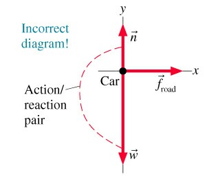
39 which of the four drawings is a correct force diagram for this problem?
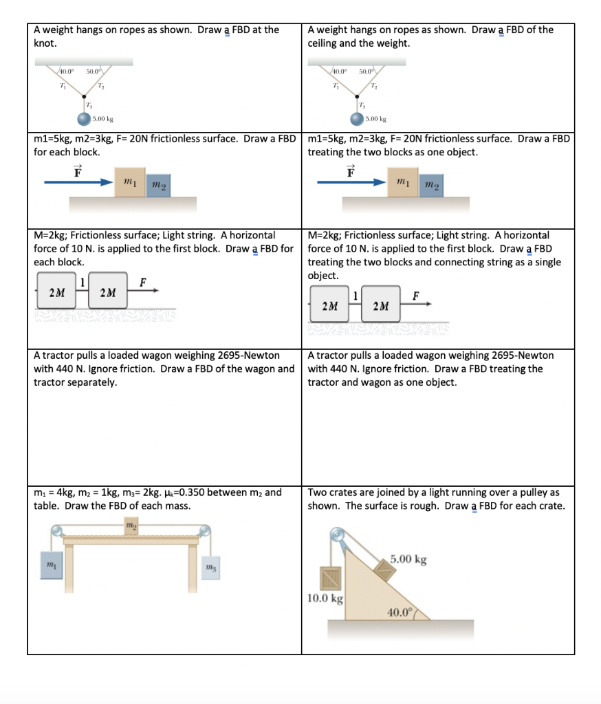
Drawing Free-Body Diagrams. Free-body diagrams are diagrams used to show the relative magnitude and direction of all forces acting upon an object in a given situation. A free-body diagram is a special example of the vector diagrams that were discussed in an earlier unit. These diagrams will be used throughout our study of physics.
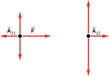
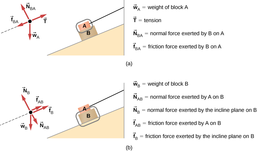
Figure 5.32 (a) The free-body diagram for isolated object A. (b) The free-body diagram for isolated object B. Comparing the two drawings, we see that friction acts in the opposite direction in the two figures. Because object A experiences a force that tends to pull it to the right, friction must act to the left. Because object B experiences a component of its weight that pulls it to the left ...
Check out http://www.engineer4free.com/structural-analysis for more free structural analysis tutorials. The course covers shear force and bending moment diag...

Which of the four drawings is a correct force diagram for this problem?
Variation of shear force and bending moment diagrams S.N Point Load UDL UVL Shear Force Constant Linear Parabolic Bending Moment Linear parabolic Cubic WORKED EXAMPLES 1) A cantilever beam of length 2 m carries the point loads as shown in Fig. Draw the shear force and B.M. diagrams for the cantilever beam. Shear Force Diagram S.F. at D, F D
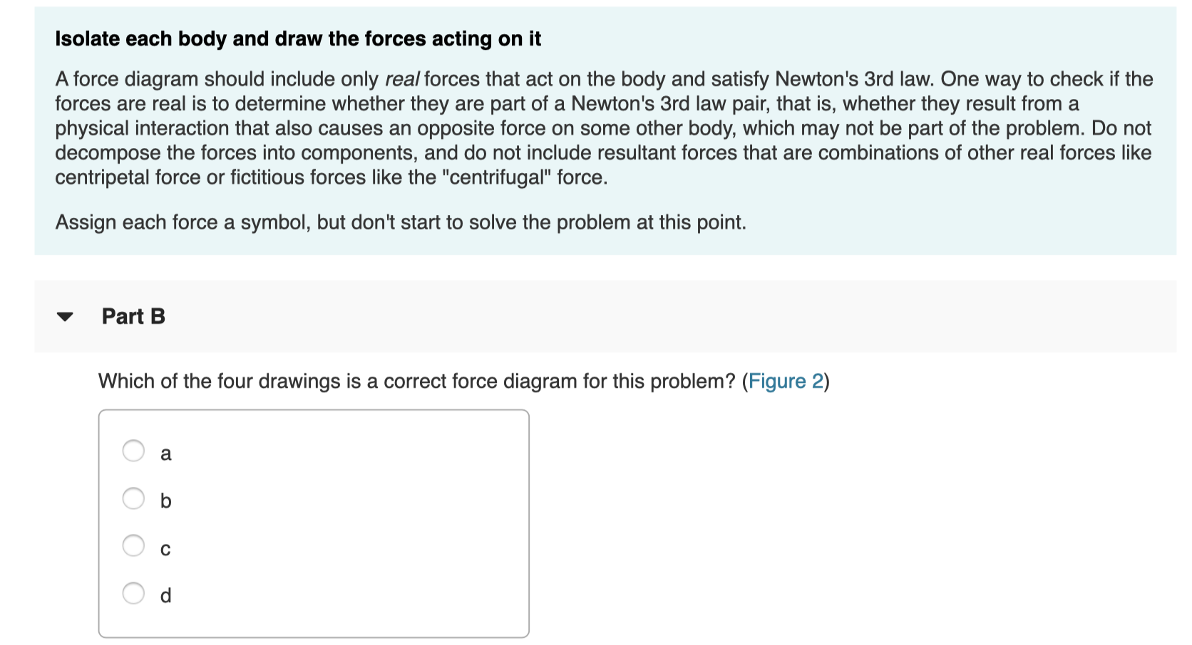
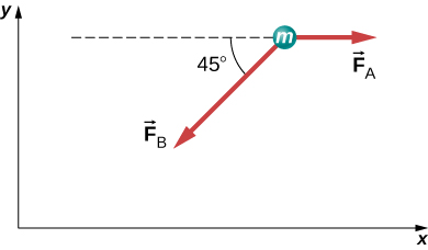
Express your answer in terms of some or all of the variables m2 and g . Part B Which of the four drawings is a correct force diagram for this problem? (Figure 2) Part C Given the criteria just described, what orientation of the coordinate axes would be best to use in this problem?
Correct Choose a coordinate system for each body Newton's 2nd law,, is a vector equation.To add or subtract vectors it is often easiest to decompose each vector into components. Whereas a particular set of vector components is only valid in a particular coordinate system, the vector equality holds in any coordinate system, giving you freedom to pick a coordinate system that most simplifies the ...
Which of the four drawings is a correct force diagram for this problem?.
Draw a free-body diagram for the object, including only the forces that act on it. When suitable, represent the forces in terms of their components in the chosen reference frame. As you do this for each force, cross out the original force so that you do not erroneously include the same force twice in equations.
Part B Which of the four drawings is a correct force diagram for this problem? ANSWER: Correct Choose a coordinate system for each body Newton's 2nd law, , is a vector equation. To add or subtract vectors it is often easiest to decompose each vector into components.
Tech A says that wiring diagrams are essentially a map of all of the electrical components and their connections. Tech B says that in many cases, each wire in wire harnesses use two colors; the first one is the solid color, and the second one is the stripe.
directly on the diagram. Pertinent dimensions may also be represented for convenience. Note, however, that the free-body diagram serves the purpose of focusing accurate attention on the action of the external forces; therefore, the diagram should not be cluttered with excessive information. Force arrows
1. Draw a rough diagram of the object in question 2. Only draw the forces on the object 3. Draw the forces roughly at the point applied 4. Apply Newton's 2nd Law to your diagram Freebody Diagrams FBD of the box In this diagram, where is the force of the box on the man? F man-box F floor-box F grav-box
4. Draw all of the forces so that their tails are at the dot and their heads point in the direction of the force. 5. Label all of the forces Ex. 1: Draw a free-body diagram for the example of a hand holding a block against the wall that is also suspended by a string. Solution: The block is represented as a point. We have four forces: tension ...
The free-body diagrams are shown in Figure 9.4. Note that there is no normal force, because the blocks are not in contact with a solid object. Instead, they are supported by the fluid. We call the upward force applied by a fluid to an object in that fluid the buoyant force, which we symbolize as .
The bending moment diagram is a series of straight lines between loads. The slope of lines is equal to the shearing force between the loading points. 2.4 Uniformly Distributed Loads Problem 2. Draw the SF and BM diagrams for a simply supported beam of length l carrying a
oor. The force of friction on the box is directed toward the A. left B. right C. ceiling D. oor 12. The force required to start an object sliding across a uniform horizontal surface is larger than the force required to keep the object sliding at a constant velocity. The magnitudes of the required forces are di erent in these situations because the
Figure 5.32 (a) The free-body diagram for isolated object A. (b) The free-body diagram for isolated object B. Comparing the two drawings, we see that friction acts in the opposite direction in the two figures. Because object A experiences a force that tends to pull it to the right, friction must act to the left. Because object B experiences a component of its weight that pulls it to the left ...
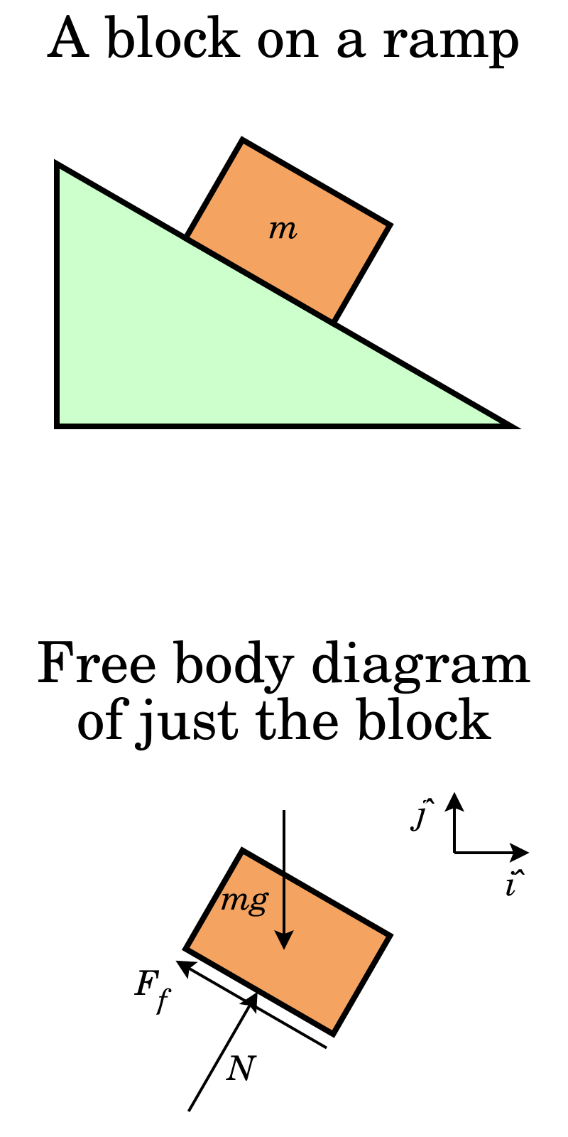
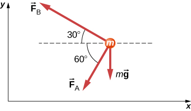
Problem 2 A particle of mass 5 Kg rests on a 30° inclined plane with the horizontal. A force F a of magnitude 30 N acts on the particle in the direction parallel and up the inclined plane. a) Draw a Free Body Diagram including the particle, the inclined plane and all forces acting on the particle with their labels.
Problem 10: Bending Moment and Shear force A beam with a hinge is loaded as above. Draw the shear force and bending moment diagram. Solution: Concept: A hinge can transfer axial force and shear force but not bending moment. So, bending moment at the hinge location is zero. Also, without the hinge, the system is statically indeterminate (to a ...
![harkerphysics [licensed for non-commercial use only] / Balanced ...](http://harkerphysics.pbworks.com/f/Freebody%20Diagram%20%232%20-%2020RomaG%20(2).png)
Harkerphysics [licensed for non-commercial use only] / balanced ...
4.0 Building Shear and Moment Diagrams. In the last section we worked out how to evaluate the internal shear force and bending moment at a discrete location using imaginary cuts. But to draw a shear force and bending moment diagram, we need to know how these values change across the structure.
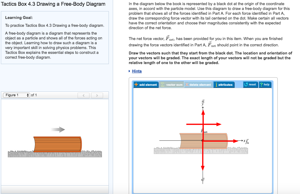
Solved tactics box 4.3 drawing a free-body diagram in the | chegg.com
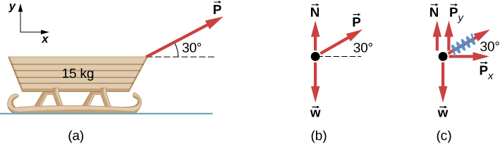
unit 2 - ap physics - leonard. The force diagram above shows a box accelerating to the right on a horizontal surface of negligible friction. The tension T is exerted at an angle of 30° above the horizontal. If μ is the coefficient of kinetic friction between the box and the surface, which of the following is a correct mathematical equation ...
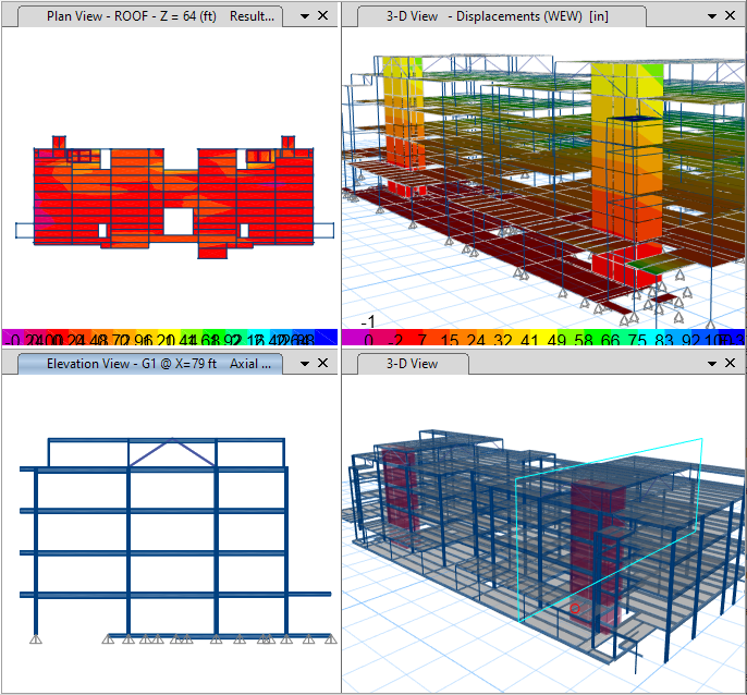
Etabs features | building analysis and design
Ftable, "table force," or any other label indicating the force is "normal" or comes from the table 1 point For correct gravitational forces with acceptable label on both diagrams: Fg, Fgrav, W, mg, mgA, "gravity," "grav force," but NOT G or g, and no extraneous forces on either diagram 1 point
Free body diagram - wikipedia
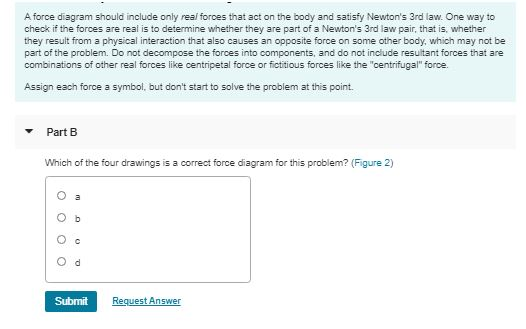
SubmitMy AnswersGive Up. Incorrect; Try Again; 4 attempts remaining. The correct answer involves the variable m2, which was not part of your answer.. Isolate each body and draw the forces acting on it. A force diagram should include only real forces that act on the body and satisfy Newton's 3rd law. One way to check if the forces are real is to detrmine whether they are part of a Newton's 3rd ...

Fishbone diagram explained | reliable plant
Sample problem 4.2 The simply supported beam in Fig. (a) is loaded by the clockwise couple C 0 at B. (1) Derive the shear and bending moment equations. And (2) draw the shear force and bending moment diagrams. Neglect the weight of the beam. The support reactions A and C have been computed, and their values are shown in Fig. (a). Solution Part 1
Solved learning goal: to learn a systematic approach to | chegg.com
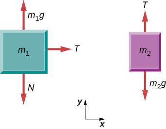
Example 8 : A system with two blocks, an inclined plane and a pulley. A) free body diagram for block m 1 (left of figure below) 1) The weight W1 exerted by the earth on the box. 2) The normal force N. 3) The force of friction Fk. 4) The tension force T exerted by the string on the block m1. B) free body diagram of block m 2 (right of figure below)
5.7 drawing free-body diagrams | university physics volume 1
Which of the four drawings is a correct force diagram for this problem? ANSWER: Correct Choose a coordinate system for each body Newton's 2nd law, , is a vector equation. To add or subtract vectors it is often easiest to decompose each vector into components. Whereas a particular set of vector components is only valid in a particular coordinate ...
Double trouble: two body problems
Drawing a correct free-body diagram is the first and most important step in the process of solving an equilibrium problem. It is the basis for all the equilibrium equations you will write; if your free-body diagram is incorrect then your equations, analysis, and solutions will be wrong as well.
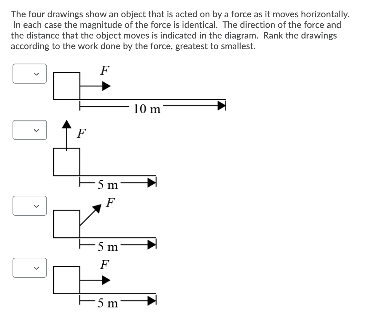
Solved the four drawings show an object that is acted on by ...
Problem P4.20: The front loader with mass 4.5 Mg is shown in side-view as it lifts a 0.75 Mg load of gravel, (a) Draw a free body diagram of the front loader, (b) Determine the contact forces between the wheels and the ground, (c) How heavy a load can be carried
Solved question 1 learning goal: to learn a systematic | chegg.com
Free-Body Diagram: (Three-force bo PROBLEM 4.63 Using the method of Sec. 4.7, solve problem 4.22b. PROBLEM 4.22 Determine the reactions at A and B when (a) IS o, 62.5 1b The line Of action at A must pass through C, where B and the 75-1b load intersect. In triangle ACE: triangle -15 10 in. tan 6 = 12 in. (75 1b) tan B -62.51b
Using force arrows in physics diagrams - video & lesson transcript ...
Step 1 - Sketch a diagram of the situation and a free-body diagram of the book. These diagrams are shown in Figure 5.1. Figure 5.1: A diagram of the sliding book and a free-body diagram showing the forces acting on the book as it slides. The Earth applies a downward force of gravity on the book, while the table applies a contact force.
Solved free-body diagrams instructions when analyzing | chegg.com
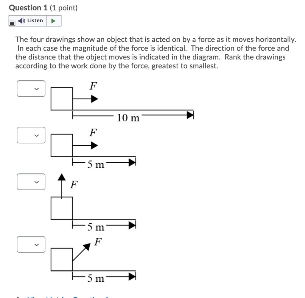
Solved question 1 (1 point) listen the four drawings show an ...
5.7 drawing free-body diagrams | university physics volume 1
5.7 drawing free-body diagrams – university physics volume 1
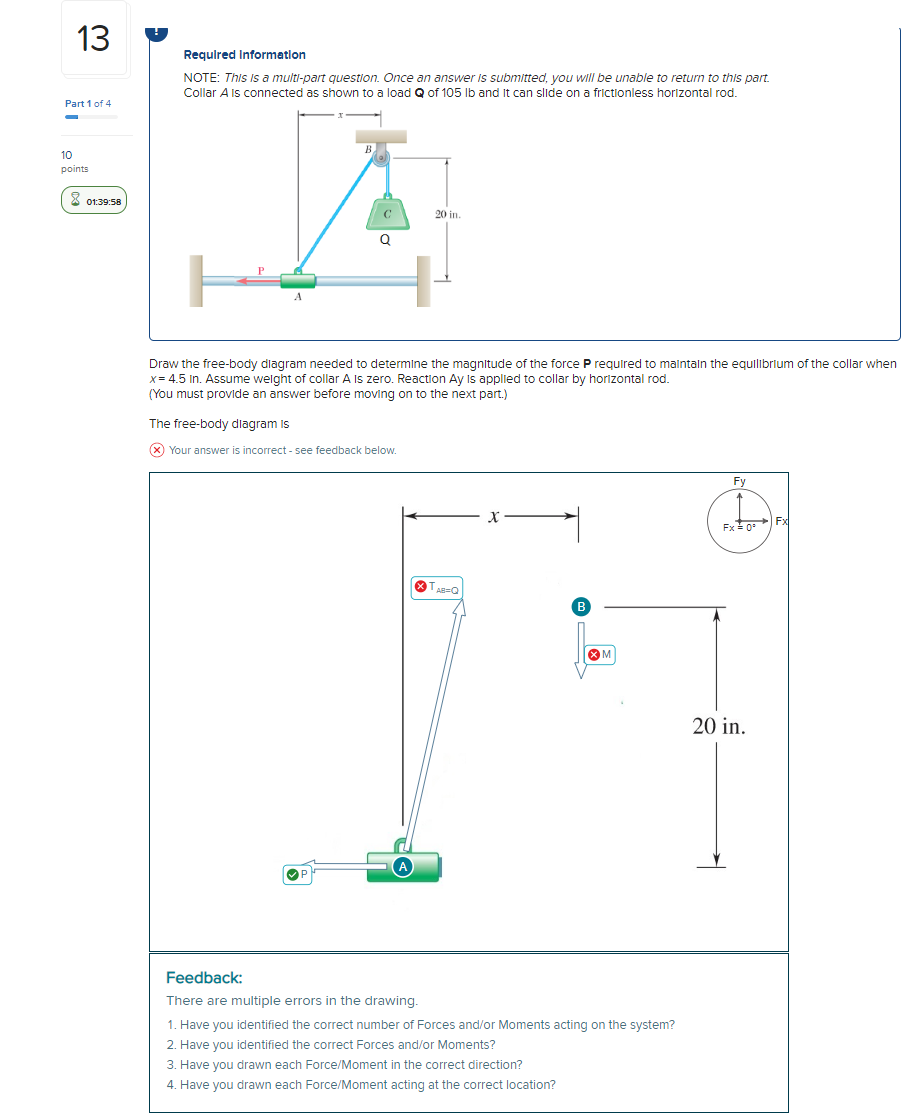
Solved 13 required information note: this is a multi-part | chegg.com
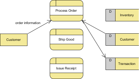
What is data flow diagram (dfd)? how to draw dfd?
5.7 drawing free-body diagrams | university physics volume 1
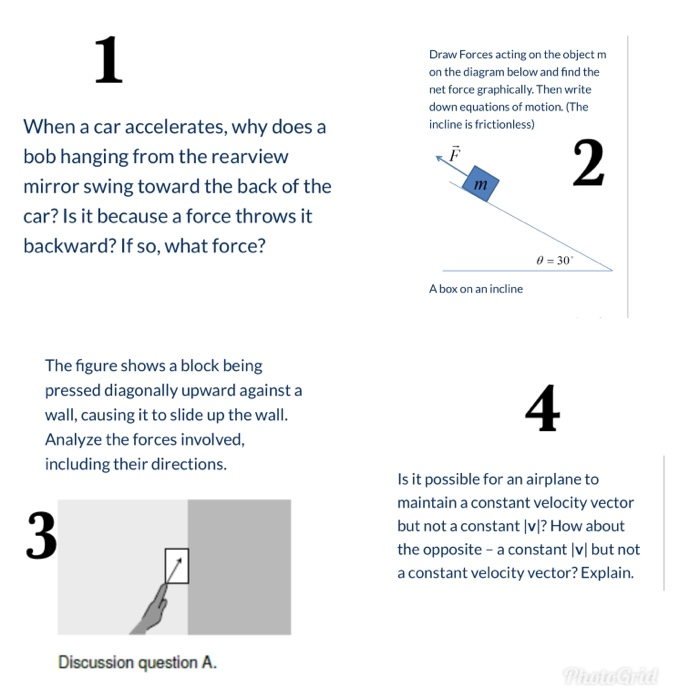
Solved draw forces acting on the object m on the diagram | chegg.com

Sph4c
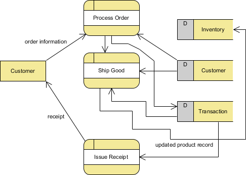
What is data flow diagram (dfd)? how to draw dfd?
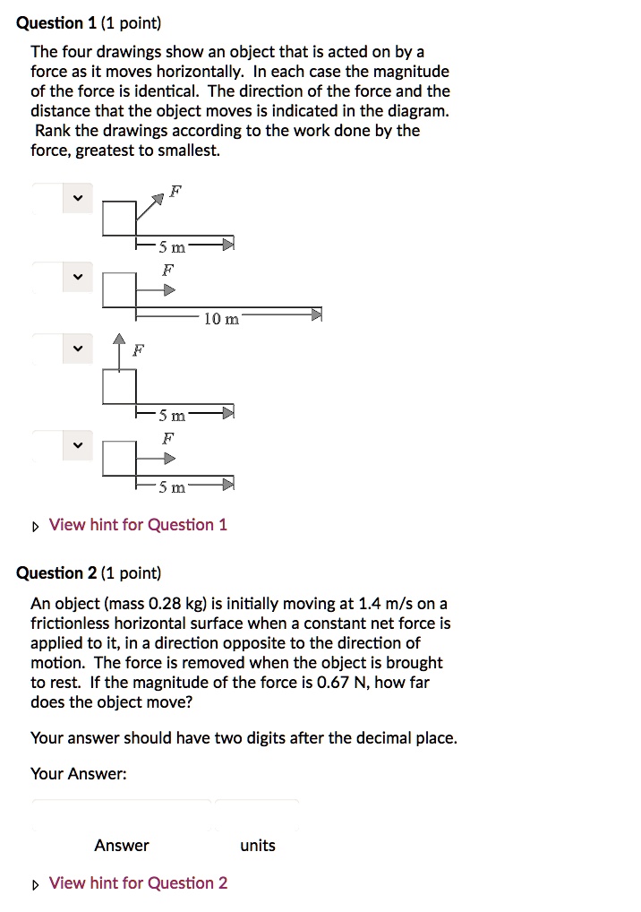
Solved:question 1 (1 point) the four drawings show an object that ...
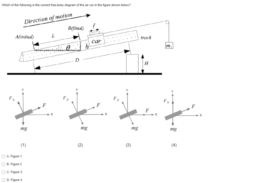
Solved which of the following is the correct free-body | chegg.com

Question 3 (identifying forces) you are standing on th… - itprospt

Calculating resultant forces vector diagrams graphs work done ...
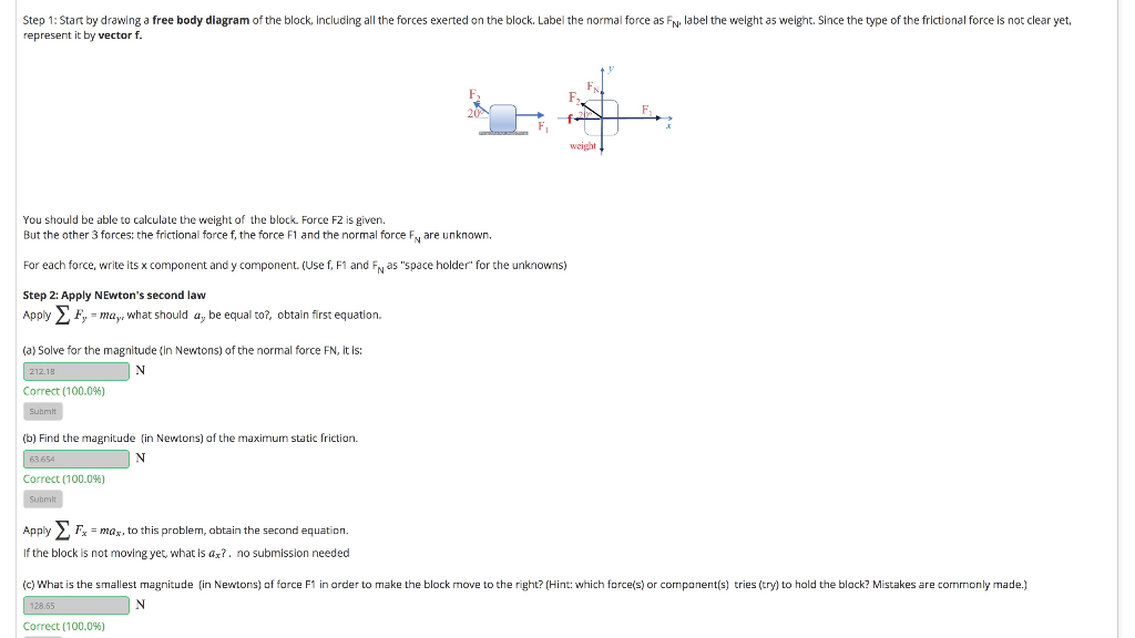
Step 1: start by drawing a free body diagram of the | chegg.com
W question 1 correct learning goal: to practice tactics box 4.3 ...

9 important questions about smart issues answered
Solved a student draws the flawed free-body diagram shown in ...

Universe | free full-text | numerical investigation for periodic ...

How to learn to draw: stage one, manual skills

Using force arrows in physics diagrams video

Breaking down forces for free body diagrams (video) | khan academy
5.7 drawing free-body diagrams – university physics volume 1
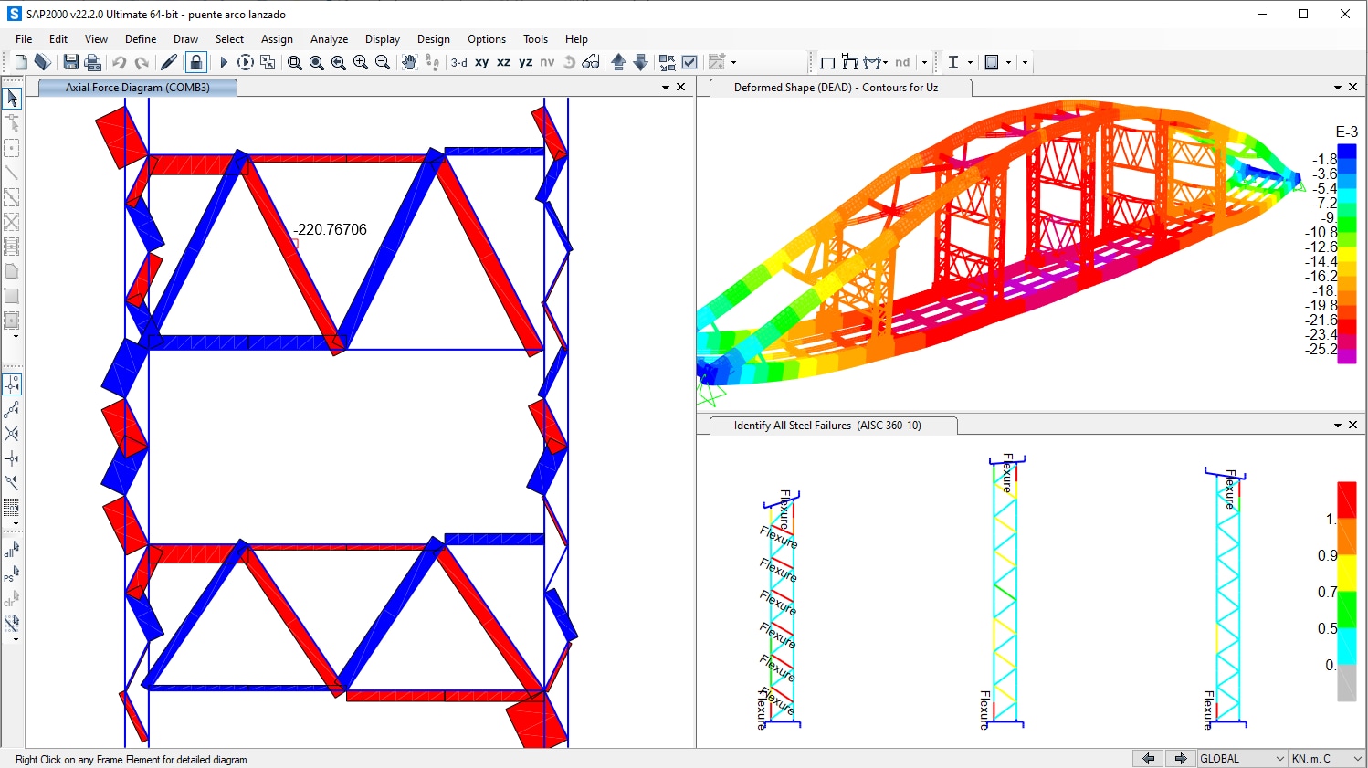
Sap2000 features | structural analysis and design
5.7 drawing free-body diagrams – university physics volume 1
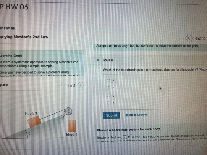
Phw 06 p hw 06 plying newton's 2nd law 6 of 10 assign | chegg.com
5.7 drawing free-body diagrams – university physics volume 1
0 Response to "39 which of the four drawings is a correct force diagram for this problem?"
Post a Comment