38 three way valve diagram
2 way and 3 way Zone Valves Piping Diagrams 2Way3WayPipingDiagram 22 June 2011 COIL A B A B COIL A B A B COIL A B A B C L OI L I CO 3 WAY - V320, V325, V345 DIVERTING VALVE BODIES The diverting valve body is installed on the supply side of the coil. The water diverts in the valve and mixes in the “T” the flow enters 3-1/2 inches (89 mm) with stem down 1-3/8 in. (35 mm) bonnet size c7961 a b a b in out in to controller mixing valve stem up increases b to ab flow c7960 fig. 4. v5013b, d, and f flow diagram. a a b out in b out to controller diverting valve stem up increases ab to a flow c7962 to return supply water to coil fig. 5. v5013c and e flow diagram.
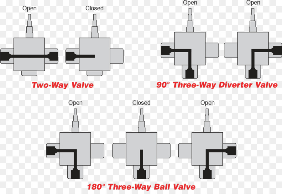
A slightly different three-way valve design could divert fuel flowing from one tank to another tank while still being able to shut off the flow of fuel entirely if needed. When choosing the right three-way ball valve, it is important to both understand the key three-way valve design options and plan how the valves will be used. First, some basics.

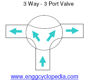
Three way valve diagram
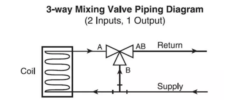
Apr 30, 2020 · Honeywell 3 Way Valve Wiring Diagram. Honeywell 3 Way Valve Wiring Diagram – wiring diagram is a simplified enjoyable pictorial representation of an electrical circuit. It shows the components of the circuit as simplified shapes, and the capability and signal friends in the company of the devices. Three-Way Diverting Valve Piping Diagram (1 Input, 2 Outputs) A B AB Supply Incorrect Piping WARNING! Do Not Pipe in this manner! Note Valve Porting! Flow is not possible from A to AB. If B port is not piped as the common port, the valve must be re-piped. These valves are intended for closed loop Three-way mixing valve operation–coil bypass. Three-way valves maintain constant flow in the piping. As the temperature requirements change, the volume of the fluid in the coil varies. AB A B M11761 HEATING COIL FULL HEAT 5 GPM 5 GPM 2.5 GPM 5 GAL./MIN. AB A B PROPORTIONED HEAT 2.5 GPM SUPPLY MAIN RETURN MAIN 5 GPM 5 GPM AB A B NO
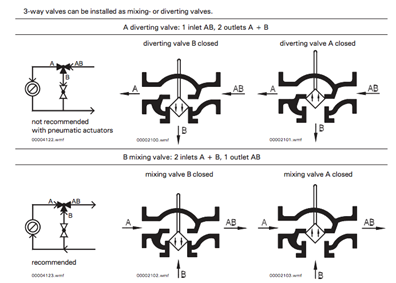
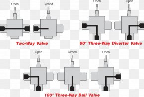
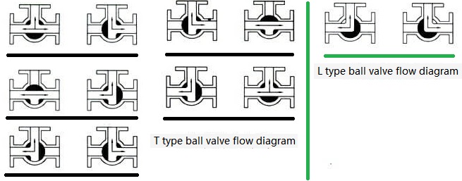
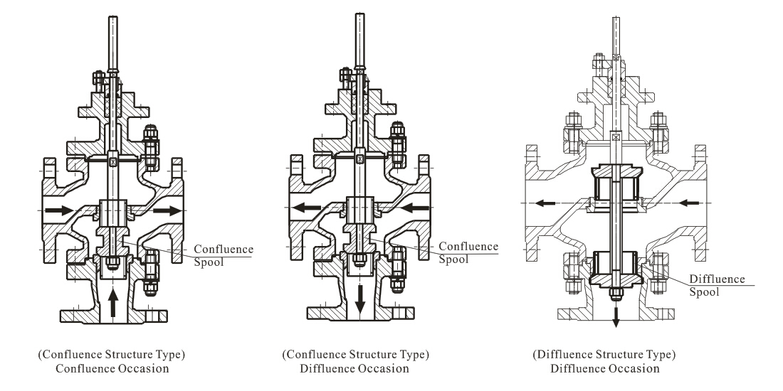
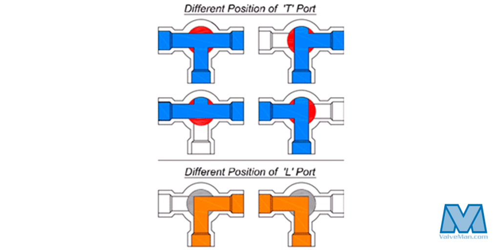
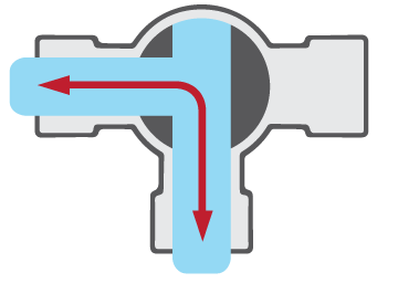
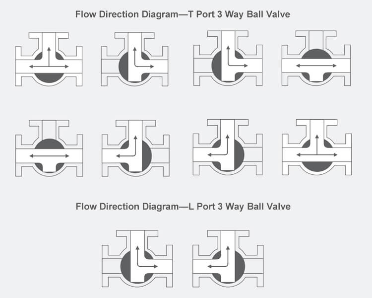
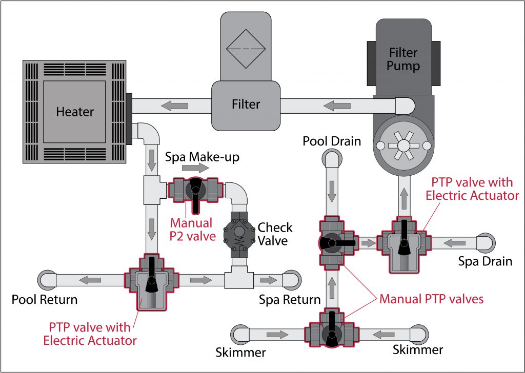
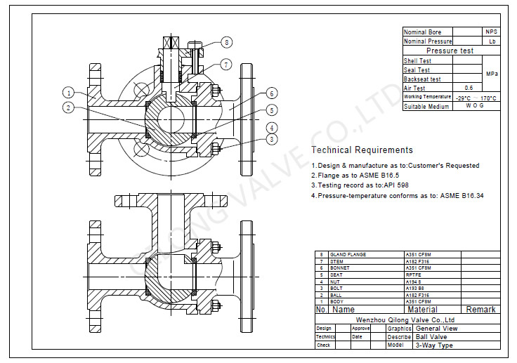
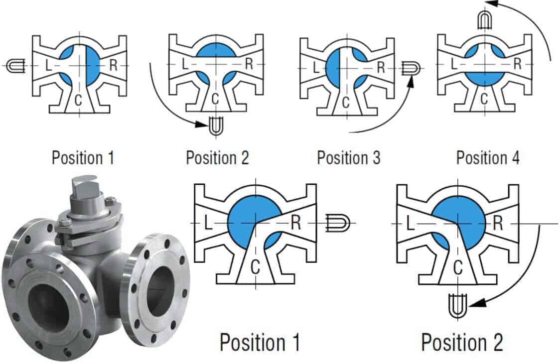
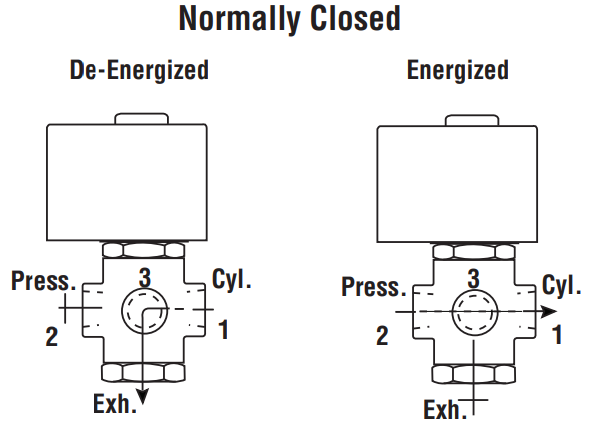
Three way valve diagram. There are two basic types of three-way valves: mixing valves (two inlets, one outlet) and diverting valves (one inlet, two outlets). The type of three-way valve selected will determine its location in the system. S R Outlet N.O. N.C. Inlet Outlet Coil Figure 1: Diverting Valve in a Bypass Application Piped N.C. to Coil Diverting valves in ... Three-way ball valves simplify gas and fluid flow control. The choice of flow pattern or valve ball porting (T-port vs L-port) provides specific options. This chart illustrates how differences between L-pattern and T-pattern flow plus how handle positio n and range of handle rotation combine with porting to control flow. 3-way Directional Control Solenoid Valves. A 3-way directional control solenoid valve has 3 pipe connections: the cavity port, the body orifice port and the stop port. It has 2 orifices: the body orifice and the stop orifice, one of which is always open. This allows for 2 paths of flow. Energizing the valve raises or lowers the plunger. Sep 25, 2020 · Three-way valve structure: Three-way valves are generally divided into L-type and T-type. The T-shape can connect three orthogonal pipelines with each other and cut off the third channel, which can split and merge. The L shape can only connect two orthogonal pipes, and cannot maintain the third pipe to communicate with each other at the same time.
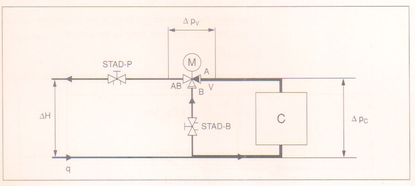
The sketch below shows a three-way diverting valve system. As the temperature from the terminal unit or coil is satisfied, the flow rate is reduced in the coil and the flow is diverted to the bypass. When the coil is completely satisfied, the resultant return temperature to the mains is equal to the supply temperature. c. Throttled valve d. Combination valves (3- or 4-way valve) e. Locked-closed valve f. Locked-open valve g. Fail-open valve h. Fail-closed valve i. Fail-as-is valve 1.10 Given an engineering P&ID, IDENTIFY components and DETERMINE the flowpath(s) for a given valve lineup. 1.11 IDENTIFY the symbols used on engineering fluid power drawings for the Three-way mixing valve operation–coil bypass. Three-way valves maintain constant flow in the piping. As the temperature requirements change, the volume of the fluid in the coil varies. AB A B M11761 HEATING COIL FULL HEAT 5 GPM 5 GPM 2.5 GPM 5 GAL./MIN. AB A B PROPORTIONED HEAT 2.5 GPM SUPPLY MAIN RETURN MAIN 5 GPM 5 GPM AB A B NO Three-Way Diverting Valve Piping Diagram (1 Input, 2 Outputs) A B AB Supply Incorrect Piping WARNING! Do Not Pipe in this manner! Note Valve Porting! Flow is not possible from A to AB. If B port is not piped as the common port, the valve must be re-piped. These valves are intended for closed loop
Apr 30, 2020 · Honeywell 3 Way Valve Wiring Diagram. Honeywell 3 Way Valve Wiring Diagram – wiring diagram is a simplified enjoyable pictorial representation of an electrical circuit. It shows the components of the circuit as simplified shapes, and the capability and signal friends in the company of the devices.


0 Response to "38 three way valve diagram"
Post a Comment