38 fm transmitter block diagram
The FM Transmitter produces a range of VHF from 88 HZ to 108 MHZ. Block Diagram for FM transmitter circuit. Components required for FM transmitter circuit are modulator, oscillator, RF-Amplifier, Audio pre-amplifier, microphone and antenna. The Diagram shows the Block diagram for FM transmitter circuit. A block diagram of a simple continuous wave (CW) transmitter is shown in Figure 6. The first block is the conventional crystal oscillator and then the final power amplifier. A power supply is provided for the oscillator and the final power amplifier. Figure 6. A block diagram representing various stages of a basic continuous wave radio transmitter.
FM Transmitter FM Modulation using VCO Block Diagram Chipset 4046 PLL 4046 VCO Characteristic Schematic PCB Layout Considerations PCB Layout Measured Results FM Receiver FM Demodulation using PLL Loop Filter Design VCO Design Block Diagram Chipset 4046 PLL Schematic PCB Layout Superheterodyne FM Receiver Block Diagram Chipset TDA7000 IF Filter Quadrature Demodulator IF Harmonic Distortion IF ...

Fm transmitter block diagram
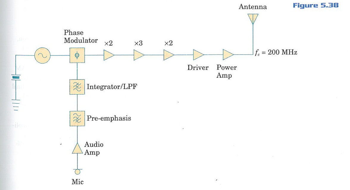
FM Transmitter Block Diagram. As the block diagram above illustrates, the integration of a message signal results in an equation for phase with respect to time. This equation is defined by the following equation: where k f is the frequency sensitivity. Again, the resulting modulation that must occur is phase modulation, which involves changing ... Fig. 1 shows the simplified block diagram of the PLL based FM audio transmitter. The PLL sets the carrier frequency, and the modulation is applied directly at ... The block diagram of NBFM modulator is shown in the following figure. Here, the integrator is used to integrate the modulating signal m ( t). The carrier signal A c cos. . ( 2 π f c t) is the phase shifted by − 90 0 to get A c sin. . ( 2 π f c t) with the help of − 90 0 phase shifter. The product modulator has two inputs ∫ m ( t ...
Fm transmitter block diagram. FM Transmitter Working Principle. The main function of an FM Transmitter Circuit is to transmit the sound using radio waves. So, at first, an FM Transmitter Circuit converts the sound or audio into radio wave then it transmit. You can see, in the block diagram of the FM Transmitter, the first block is the Microphone. Block Diagram of FM Receiver with Explanation. Standard broadcast for FM is 88-108 MHz. The maximum permissible deviation is 200 KHz. In FM the intermediate frequency is 10.7 MHz. In FM the operating frequencies are much higher than that in AM. It additionally contain a de-emphasis and limiter circuit. The method of demodulation is totally ... Fig. 5 shows a block diagram of a CW type of transmitter. We have included fre- quency doublers and amplifiers to provide a general idea of what might be found in a transmitter circuit. The frequency multipliers could be triplers or even quadruplers, if that would aid us in arriving at the desired transmitting frequency. On The circuit can also be used as a remote control transmitter. FM Demodulator using PLL - This is a good circuit of an FM demodulator with a schematic diagram, a design of FM demodulator, and working of PLL with block diagram. This will definitely be useful for your educational purposes. FM stereo demodulator using AN7415 - Stereo ...
Block diagram of an FM (frequency modulated) transmitter is given on Pic.2.4. Information being transferred, i.e. the modulating signal, is a signal from some LF source. it is being amplified in LF amplifier and then led into the HF oscillator, where the carrier signal is being created. The carrier is a HF voltage of constant amplitude, whose ... Block diagram of FM transmitter and receiver and its explanation. FM transmitter. Frequency Modulation is the process in which the frequency of the carrier signal is varied by the modulating signal while the amplitude remains constant. Using Reactance modulator direct method. FM Transmitters - Example • Assume fc drift 40 ppm/degree (40 x 5.1 = +/- 204Hz) ! 3672 Hz at the antenna; • Thus, following 5 degree temp. change ! freq. drift will be 18.36 KHz at the antenna! Block Diagram of FM Transmitter. The following image shows the block diagram of the FM transmitter and the required components of the FM transmitter are; microphone, audio pre-amplifier, modulator, oscillator, RF- amplifier, and antenna. There are two frequencies in the FM signal, the first one is the carrier frequency and the other one is ...
Radio Transmitter Block Diagram. This block diagram of a radio transmitter in a communication system is very simple and basic. It is generalised for AM and FM types of modulation, and consists of four subsystems. Communication is the transfer of meaningful information from one location to another. We start with the conversion of sound waves in ... Armstrong FM Transmitter Block Diagram. The crystal-controlled carrier oscillator signal is directed to two circuits in parallel. This signal (usually a sine wave) is established as the reference past carrier signal and is assigned a value 0°. Block diagram of television transmitter. The basic television Broadcast transmitter block diagram is shown in figure (a). The block diagram can be broadly divided into two separate section, viz., one that - Generates an electronic signal (called video signal) corresponding to the actual picture and then uses this video signal to modulate an R-F carrier so as to be applied to the transmitting ... FDM Transmitter. Fig.2 shows the block diagram of an FDM transmitter . Fig. 2 : FDM Transmitter. The signals which are to be multiplexed will each modulate a separate carrier .The type of modulation can be AM, SSB, FM or PM . The modulated signals are then added together to form a complex signal which is transmitted over a single channel .
Marina City Theater, Chicago, Illinois, Roof and Partial Concrete Frame Development Drawing (1961-1962) // Bertrand Goldberg American, 1913-1997
About Press Copyright Contact us Creators Advertise Developers Terms Privacy Policy & Safety How YouTube works Test new features Press Copyright Contact us Creators ...

minimalist photography of high-rise building window
A FM transmitter is a device that uses the principles of frequency modulation to broadcast sound supplied at its input. Typical FM transmitter design's usually follow the block diagram below; The signal strength of audio inputs into the transmitter is usually low therefore an amplifier is usually built to bring the signal level up.

1: Block diagram of a typical radio transmitter | Download ...
Fig. 4 Hybrid block diagram of a composite FM transmitter. The frequency of Yl is multiplied by a factor of eight as the various doubler stages amplify the signal. Similarly, the deviation at Yl is increased by a factor of eight during the multiplication process Class-C stages are used throughout the transmittar RF section.

Lake Chuzenji, Nikko (Nikko Chuzenjiko) (1930) // Kawase Hasui 川瀬 巴水 Japanese, 1883-1957
Block diagram of a low level FM broadcast transmitter is shown in figure. The master oscillator generates the RF signal (carrier) required for modulation. Master oscillator is generally a well defined LC oscillator. The buffer amplifier is used to make the oscillator frequency free from the loading of the next stages.

MIZAR300 300 Watt FM Broadcast Transmitter Schematics Schematic package Elettronika S.r.l.
FM Transmitter Circuit Principle: FM transmission is done by the process of audio pre amplification, modulation and then transmission. Here we have adapted the same formula by first amplifying the audio signal, generating a carrier signal using an oscillating and then modulating the carrier signal with the amplified audio signal.
4. (TCO 4) Answer The Questions With Respect To Th ...
F.M. Transmitter Tutorial - Block Diagrams - Electronics Circuit and Tutorials - Hobby Science Projects - The microphone converts sound pressure wave to ...

Fishing Boats at Choshi in Shimosa (Soshu Choshi) from the series "One Thousand Pictures of the Ocean (Chie no umi)" (c. 1833/34) // Katsushika Hokusai 葛飾 北斎 Japanese, 1760-1849
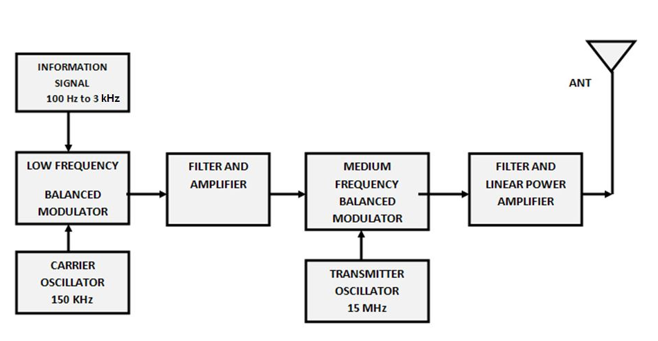
Below figure's show the block diagram of high-level and low-level transmitters. The basic difference between the two transmitters is the power amplification of the carrier and modulating signals. Figure (a) shows the block diagram of high-level AM transmitter.

Communication Protocols Assignments: Block diagram of AM ...
Frequency modulated systems are operated usually at a frequency above 40 MHz. Frequency modulated broadcasting is done in television sound, mobile radio etc....

Panel (c. 1815) // Printed at the Bannister Hall Print Works (English, active 1799-1840) England, Lancashire, Preston
FM Transmitter. FM transmitter is the whole unit, which takes the audio signal as an input and delivers FM wave to the antenna as an output to be transmitted. The block diagram of FM transmitter is shown in the following figure. The working of FM transmitter can be explained as follows.

Block Diagrams
FM transmitter FM Transmitter Block Diagram Direct Method. Using Reactance modulator direct method. The FM transmitter has three basic sections. The exciter section contains the carrier oscillator, reactance modulator and the buffer amplifier.; The frequency multiplier section, which features several frequency multipliers.; The power output section, which includes a low-

pencils on grayscale photography
• Draw a block diagram of an FM receiver, showing the frequency and type of signal at each major test point. • Explain the operation and alignment of Foster-Seeley/Ratio, PLL, and quadrature FM detector circuits. • Describe the features of noise-suppressing circuits in an FM receiver.

Block diagram of the CDMA transmitter implemented ...
3.1 Block diagram of standard FM transmitter 11 3.2 The functional blocks diagram of FM generation 13 3.3 The simple microphone modulator for FM generation 13 3.4 Direct FM modulator using varactor diode 15 3.5 The relationship between junction capacitance and reverse 15 bias voltage ...

Block diagram of the FM-CW analog transmitter and receiver ...
It's not a circuit diagram, but a block diagram, which means it can't be used to understand the transmitter at the component level. However it can be used to aid a first level diagnosis of problems, and which circuit board or black box to replace when something fails.

860-880 North Lake Shore Drive, Electrical Riser Diagram (11/28/1949) // Ludwig Mies van der Rohe (American, born Germany, 1886–1969) Associate Architect: Holsman, Holsman, Klekamp and Taylor (American, 20th century) Associate Architect: Pace Associates (American, 20th century) Structural Engineer: Frank J. Kornacker (American, active 1940s–1950s)
The block diagram of NBFM modulator is shown in the following figure. Here, the integrator is used to integrate the modulating signal m ( t). The carrier signal A c cos. . ( 2 π f c t) is the phase shifted by − 90 0 to get A c sin. . ( 2 π f c t) with the help of − 90 0 phase shifter. The product modulator has two inputs ∫ m ( t ...
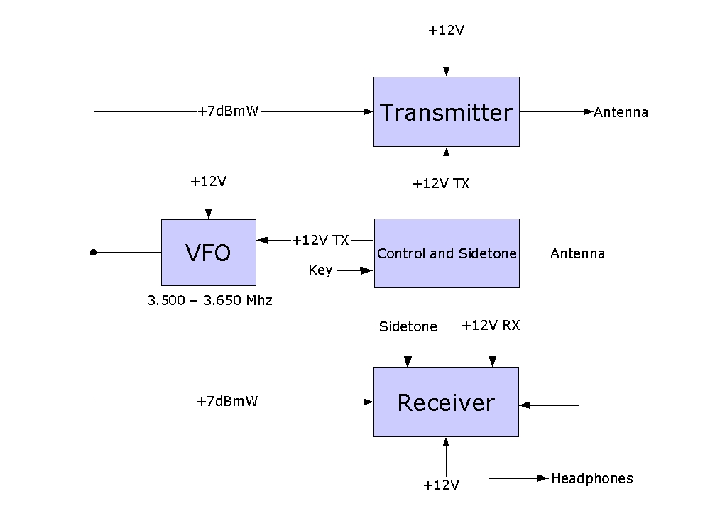
5 Watt 80 Meter QRP CW Transceiver
Fig. 1 shows the simplified block diagram of the PLL based FM audio transmitter. The PLL sets the carrier frequency, and the modulation is applied directly at ...

man in red shirt and blue jeans sitting on stair
FM Transmitter Block Diagram. As the block diagram above illustrates, the integration of a message signal results in an equation for phase with respect to time. This equation is defined by the following equation: where k f is the frequency sensitivity. Again, the resulting modulation that must occur is phase modulation, which involves changing ...

man wearing black shirt

The actors Ichikawa Omezo I (R) as Tomita Hyotaro and Otani Oniji III (L) as Kawashima Jibugoro (1794) // Toshusai Sharaku 東洲斎 写楽 Japanese, active 1794-95 Publisher: Tsutaya Juzaburo Japanese, 1748-1797

Block diagram of WLAN transmitter and receiver. | Download ...

Sharecropper (1952, printed 1970) // Elizabeth Catlett American, active in Mexico, 1915-2012
Transmitter vs Receiver | Transmitter types,Receiver types difference
Simple FM Transmitter - Electronics-Lab.com

Aaron & Me (1985) // Gay Block American, born 1942

red petaled flower

What is FM Receiver, How to build an Arduino FM Radio with ...

Portrait of Mary Block (1955–57) // Ivan Albright American, 1897–1983

Electrical and Electronics Engineering: FM transmitter ...
Radio Transmitter Block Diagram
Long range fm transmitter circuit,2 km 88-108 MHz VHF
Best FM Transmitter using 2N3904 Transistor

Digital Radio Receiver Block Diagram | Download Scientific ...

Panel (Furnishing Fabric) (c. 1815) // Printed at the Bannister Hall Print Works England, Lancashire, Preston

DIY FM Transmitter | Details | Hackaday.io

Transmitter and Receiver Block Diagram | Download ...
50.) A Block Diagram For An FM Transmitter Using I ...

Amplitude Modulated(AM) Transmitter | Fm transmitters ...
Navy Electricity and Electronics Training Series (NEETS), Module 17, 2-11 to 2-10 - RF Cafe
LT104AA FM Transmitter Block Diagram KTV Global
0 Response to "38 fm transmitter block diagram"
Post a Comment