37 powerflex 525 wiring diagram
PowerFlex 525 VFD Setup - Programming Parameters Wiring Diagram RSLogix Studio 5000 EtherNet IP Address Start StopVisit https://SolisPLC.com for more Tutoria... PowerFlex 525 AC Drive Family Power, control, flexibility and features for a wide range of applications Ideal for standalone machines and simple system integration 3 Power range: • 100-120V: 0.4 to 1.1 kW / 0.5 to 1.5 Hp • 200-240V: 0.4 to 15 kW / 0.5 to 20 Hp • 380-480V: 0.4 to 22 kW / 0.5 to 30 Hp
Wiring Block Diagram. Rockwell Automation Publication 520-TD001G-EN-E - August 2021 5 PowerFlex 520-series AC Drive Specifications ... The PowerFlex 525 drive allows for configurable closed loop control with an optional encoder card for either speed or position feedback for

Powerflex 525 wiring diagram
Both the PowerFlex 525 (2 PID inputs) and the PowerFlex 523 (1 PID input) AC Drives have the PID functionality (proportional, integral, derivative) control loops. The PID loop is used to maintain a process feedback (such as pressure, flow or tension) at a desired set point. O PowerFlex 755 AC Drive (20G11-N-B-DM1AA6K32V8) - v12.001. Ethernet patch cables. The drive will fault with. To clear a fault, press the Stop key, cycle power or set A100 [Fault Clear] to 1 or 2. For a complete listing of Faults and Alarms, refer to the PowerFlex 400 User Manual. Fault Codes. No. Fault. Description. F2. Auxiliary Input (1 ... Power Wiring 9 I/O Wiring 10 Control Terminal Block 11 Prepare For Drive Start-Up 16 Network Communication 34 Title Publication PowerFlex 520-Series Adjustable Frequency AC Drive User Manual 520-UM001 PowerFlex 4-Class Human Interface Module (HIM) DSI Quick Reference 22HIM-QR001 PowerFlex 525 Embedded EtherNet/IP Adapter User Manual 520COM-UM001
Powerflex 525 wiring diagram. PowerFlex 525 Variable Frequency Drive Basic Wiring and Parameters. PowerFlex 525 VFD DataSheet: Click Here. Within the datasheet, the user will find a lot of information about the setup of the drive. This includes wiring diagrams as well as parameters which we will be setting up shortly. Powerflex 525 Vfd Setup Programming Parameters Wiring Diagram Rslogix Studio 5000 Ethernet Ip Address Start Stop. Drive Modernization Part Vi Powerflex 40 To 525 Horizon Solutions. Powerflex 753 Ac Drives Allen Bradley United States. Drive Modernization Part V Powerflex 700 To 750 Horizon Solutions. Drive Modernization Part Iii 1305 To ... Solved: Hi, Just wondering if anyone has any drawings of Allen Bradley Power flex drives & Panel views CAD drawing that can be inserted into a 525 Drive with Contactor section on pages 1 and 22. ... PowerFlex 525, 100S, 700S-C ... In the wiring diagrams that are shown in this publication, ...
Powerflex 525 Wiring Diagram Collection. A wiring diagram is a schematic type that uses abstract illustrated symbols to show all of the components of a system. Wiring diagrams are made up of two things: symbols that represent the components of a circuit, and lines that represent the connections between them. PowerFlex 525 Configuration with Permanent Magnet Motors Step 2: Configure the Control Mode Selection PM Motor Control was added to the PowerFlex 525 in v5.xx of the firmware. The control mode selection of "4" is used for the PM motor control. The PM algorithm is basically a VHz type algorithm with alignment, stability, and efficiency Powerflex 40 Wiring Diagram. Drive modernization part vi powerflex 40 to 525 horizon solutions quick start guide control terminal block english 8 wiring diagram rockwell automation 22b frn 5 6 user manual page 10 161 appendix c rs485 dsi protocol network 1 125 160 installation 15 figure enbl 22d 40p 3 25 200 original mode adjule frequency ac ... Powerflex 525 Wiring Diagram. Further information can be found in the PowerFlex user manual UM of . The precise knowledge of the operating instructions, wiring diagram, and. PowerFlex 525 Series Keypad Navigation. Answer. This document is intended to provide the basic Parameters settings and wiring to a standalone PowerFlex AC drive.
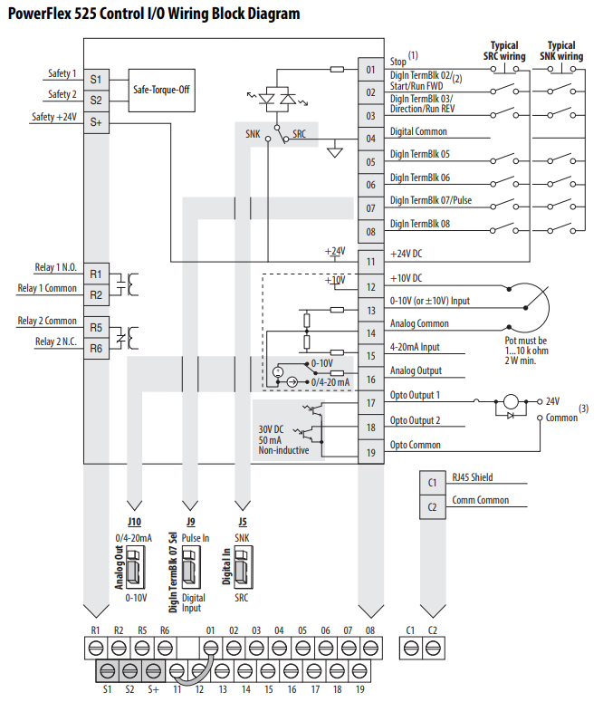
wiring, and parameters of the PowerFlex 40 and PowerFlex 40P drives to the PowerFlex 525 drive. • Chapter 3: Network Communication beginning on page 119. This chapter identifies the network options that can be migrated to the PowerFlex 525. This section also provides overview information for I/O Image for PowerFlex 525 Drives table updated. 62 CompactLogix Controller for Drive Generic Profile Ladder Logic Program Example graphic updated. 66 CompactLogix Example Ladder Logic Program Using a Drive Generic Profile for Logic Command/Reference diagram updated. 68 Important table for CompactLogix Examples updated. 71 Follow these steps to download the files for your PowerFlex 525 drive. 1. Go to the Rockwell Automation ... PowerFlex 525 Control I/O Wiring Block Diagram. PowerFlex 525 VFD Setup - Programming Parameters Wiring Diagram RSLogix Studio 5000 EtherNet IP Address Start-Stop Tutorial Links in the Comments!...
Allen-Bradley PowerFlex 525 Manual Online: Control I/O Terminal Block. 32 Control I/O Wiring Block Diagram Safety 1 S1 Safe-Torque-Off Safety 2 S2 Safety 24V S Relay 1 N.O. R1 Relay 1 Common R2 Relay 2 Common R5 Relay 2 N.C. R6 0/4-20mA 0-10V R1 R2 R5 R6 S1 S2 S Control I/O Wiring...
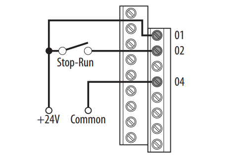
In this video we show you how to wire and configure an Allen Bradley Powerflex 525 AC Drive for 3 Wire Control such as you would see on a START/STOP circuit....
Vfd wiring diagram showing power in start stop control with plc using ladder logic controlling vfds manual inputs file jpg probotix allen bradley powerflex 525 setup programming 3 phase induction motor variable frequency drive panel Vfd Wiring Diagram Showing Power In Out And Control Device Scientific Vfd Start Stop Wiring Diagram Electrical4u How To Control Vfd… Read More »
Powerflex 525 Control I/O Wiring Block Diagram - Allen-Bradley PowerFlex 523 Quick Start Manual. Powerflex 520-series adjustable frequency ac drive.
Powerflex 525 Wiring Diagram. Print the cabling diagram off plus use highlighters in order to trace the signal. When you make use of your finger or even follow the circuit along with your eyes, it may be easy to mistrace the circuit. A single trick that I use is to print the same wiring plan off twice.
The PowerFlex 525 drive allows for the selection of 1/2 DC Bus operation , for use in critical applications where continued drive output is desired even in the event of brown out or low voltage conditions. The PowerFlex 525 drive also supports ... • Embedded safety reduces wiring and saves on installation space.
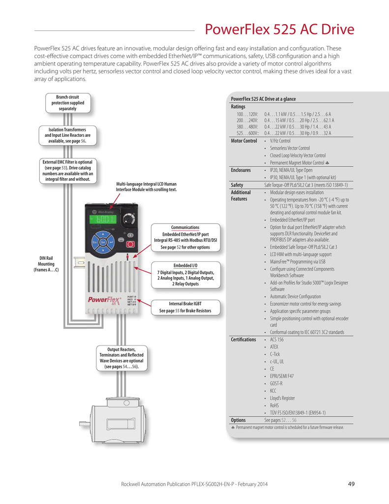
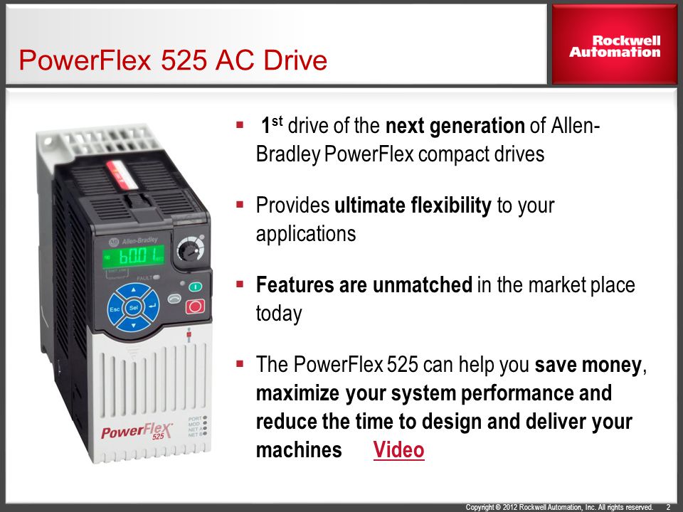
Our PowerFlex® 525 AC Drives feature an innovative, modular design to support fast and easy installation and configuration. This next generation of compact drives offers embedded EtherNet/IP™ communications, USB programming, and standard safety features.
for your feedback, Doug. In this day and age, you would think that there would. be a larger library of components included in AutoCAD Electrical. Everyone is. soft-starts, variable frequency drives, and servo drives for control systems. this change in direction of control system manufacturers.
I'm still not 100% certain the OP is asking about single phase input, three phase output. But if that's the case, on a PowerFlex 525: R, S, & T are the line power inputs on the power terminal block. If you're wanting to run on single phase input, use R & T and de-rate the drive to 1/3 of its nameplate rating. 1 person likes this. Share this post.
- PowerFlex 523, PowerFlex 523 drive or PowerFlex 523 AC drive. - PowerFlex 525, PowerFlex 525 drive or PowerFlex 525 AC drive. • Parameter numbers and names are shown in this format: • The following words are used throughout the manual to describe an action: Title Publication PowerFlex 525 Embedded EtherNet/IP Adapter 520COM-UM001
Powerflex 750 Wiring Diagram. The examples and diagrams in this manual are included solely for illustrative purposes. PowerFlex Main Control Board I/O wiring examples added. . connecting incoming power, the motor, and basic I/O to the PowerFlex® .. wiring diagram symbols used throughout various parts of the world.
PowerFlex 525 Available Inputs and Outputs. The PowerFlex 525 series variable frequency drive provides an array of I/O points that are summarized in the datasheet drawing below. PowerFlex 525 - Control I/O Wiring Diagram. From this drawing, we can identify the following elements: PowerFlex 525 Inputs. 7 x Digital Inputs.
Please refer to the manuals below for installation, troubleshooting, programming, and application techniques. Parameters may be found in the user manual, ...
Allen-Bradley PowerFlex 525 Manuals & User Guides User Manuals, Guides and Specifications for your Allen-Bradley PowerFlex 525 Adapter, Controller, DC Drives, Media Converter. Database contains 8 Allen-Bradley PowerFlex 525 Manuals (available for free online viewing or downloading in PDF): Application technique, Installation instructions ...
Wiring Block Diagram. 4 Rockwell Automation Publication 520-TD001E-EN-E - July 2016 PowerFlex 520-Series AC Drive Specifications Communications ... The PowerFlex 525 drive allows for configurable closed loop control with an optional encoder card for either speed or

China Powerflex 525 Filtered Drive 25b D1p4n114 Of Rockwell Automation China Filtered Drive Ac Drive
Chapter 1 Installation/Wiring This chapter provides information on mounting and wiring the PowerFlex 4 Drive. For information on 5/5(2). liability for actual use based on the examples and diagrams. No patent liability is assumed by Rockwell Automation, Inc. with respect to use of PowerFlex 4 User Manual, P-4 Chapter 1 Installation/Wiring.
Powerflex 525 control i/o wiring block diagram – Rockwell Automation 25B PowerFlex 520-Series Adjustable Frequency AC Drive Quick Start User Manual. Page 13.
Power Wiring 9 I/O Wiring 10 Control Terminal Block 11 Prepare For Drive Start-Up 16 Network Communication 34 Title Publication PowerFlex 520-Series Adjustable Frequency AC Drive User Manual 520-UM001 PowerFlex 4-Class Human Interface Module (HIM) DSI Quick Reference 22HIM-QR001 PowerFlex 525 Embedded EtherNet/IP Adapter User Manual 520COM-UM001
O PowerFlex 755 AC Drive (20G11-N-B-DM1AA6K32V8) - v12.001. Ethernet patch cables. The drive will fault with. To clear a fault, press the Stop key, cycle power or set A100 [Fault Clear] to 1 or 2. For a complete listing of Faults and Alarms, refer to the PowerFlex 400 User Manual. Fault Codes. No. Fault. Description. F2. Auxiliary Input (1 ...
Both the PowerFlex 525 (2 PID inputs) and the PowerFlex 523 (1 PID input) AC Drives have the PID functionality (proportional, integral, derivative) control loops. The PID loop is used to maintain a process feedback (such as pressure, flow or tension) at a desired set point.
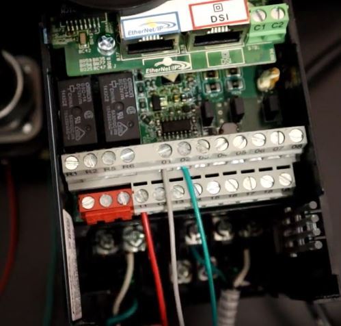
Powerflex 525 Vfd Setup Programming Parameters Wiring Diagram Rslogix Studio 5000 Ethernet Ip Address Start Stop

Powerflex 525 Vfd Setup Programming Parameters Wiring Diagram Rslogix Studio 5000 Ethernet Ip Address Start Stop






0 Response to "37 powerflex 525 wiring diagram"
Post a Comment