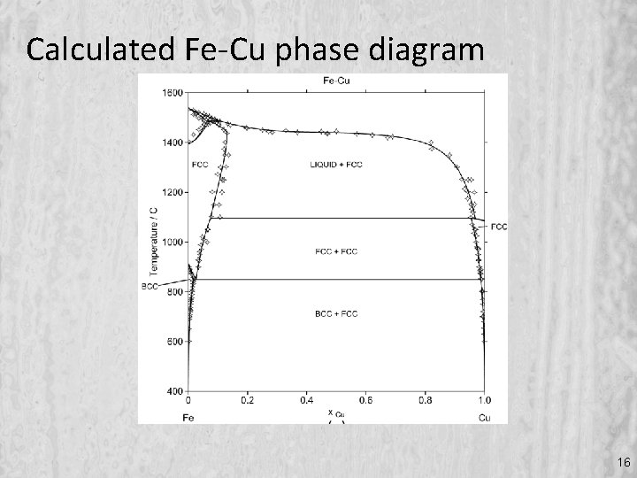
37 fe cu phase diagram
Teach Yourself Phase Diagrams A.6 HRS 03/11/2009 and Phase Transformations DEF.The equilibrium constitution is the state of lowest Gibbs free energy G, for a given composition, temperature and pressure. An alloy in this state shows no tendency to change – it is thermodynamically An Ellingham diagram is a graph showing the temperature dependence of the stability of compounds. This analysis is usually used to evaluate the ease of reduction of metal oxides and sulfides.These diagrams were first constructed by Harold Ellingham in 1944. In metallurgy, the Ellingham diagram is used to predict the equilibrium temperature between a metal, its oxide, and oxygen — and by ...
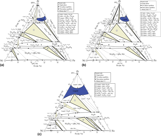
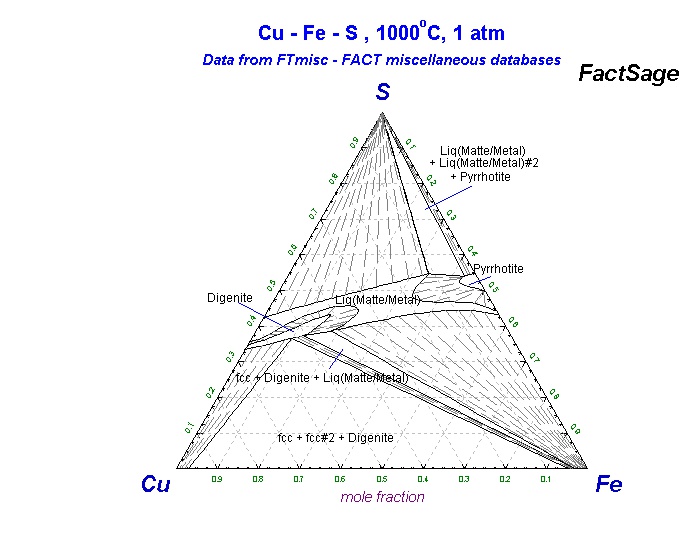
Cu-Fe-Nd Vertical Section of Ternary Phase Diagram Cite this page. Citation Phase diagram available to subscribers; If you are having trouble in accessing ...
Fe cu phase diagram
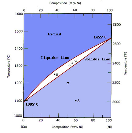
Mar 01, 2019 · Then the metastable Fe–Cu–C phase diagrams of different Cu content were calculated using the obtained dataset. Fig. 16 shows the calculated metastable Fe–Cu–C phase diagram. Cu addition causes a narrower cementite phase region. An enlarged diagram of the Fe-rich region is presented in Fig. 16c. One can see that 1 at% Cu addition causes ... ADVERTISEMENTS: In this article we will discuss about:- 1. Meaning of Phase Diagram 2. Type of Phase Diagram 3. Various Type of Phase Diagram Reaction 4. Congruent Phase Transformations 5. Influence of Alloying Elements. Meaning of Phase Diagram: A phase diagram is also called an equilibrium or constitutional diagram. It shows the relationship between temperature, […] Binary phase diagram If a system consists of two components, equilibrium of phases exist is depicted by binary phase diagram. For most systems, pressure is constant, thus independently variable parameters are –temperature and composition. Two components can be either two metals (Cu and Ni), or a metal and a compound (Fe and Fe3C), or two ...
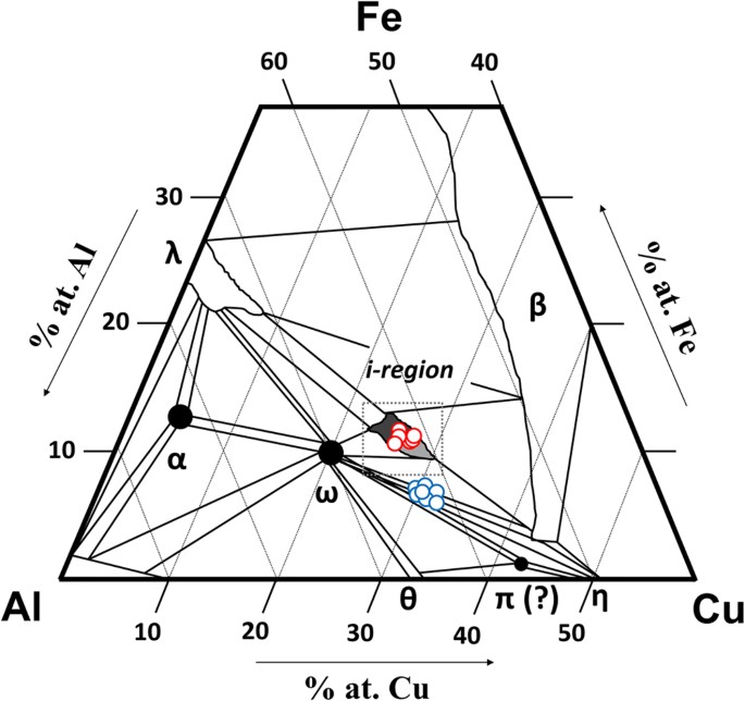
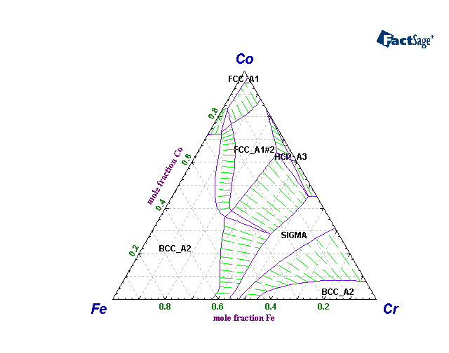
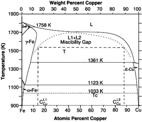
Fe cu phase diagram. A thermodynamic database of the Cu-Fe-X [X: aluminum (Al), cobalt (Co), chromium (Cr), manganese (Mn), molybdenum (Mo), niobium (Nb), nickel (Ni), vanadium (V)] systems was developed by the CALPHAD (Calculation of Phase Diagrams) method, where the Gibbs energies of solution phases such as the liquid, face-centered-cubic (fcc), body-centered-cubic (bcc), and hexagonal-close-packed (hcp) phases ... 1.7.2004 · The fcc phase field includes the composition Fe 20 Cr 20 Mn 20 Ni 20 Co 20, and is capable of dissolving substantial amounts of Nb, Ti and V, as well as smaller amounts of Cu and Ge. It presumably extends to include the fcc austenite phase in pure Fe, pure Ni and binary Fe–Ni alloys. Jan 01, 1980 · INTRODUCTION Recent phase diagram calculated on the Fe-Cu system, in general fit closely to experimental data. However, the calculation due to Kubaschewski et al. (1) yields a rather low solubility of Cu in f-iron while the calculation by Hasebe and Nishizawa (2) yields a higher solubility of Cu in y-iron especially at temperatures where y-iron ... 金属やセラミックスの状態図、エンリンガム図などの情報を提供しています。 一部、不確かなものもありますので、自己 ...
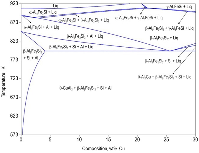
Phase Diagram Resources from ASM International. Alloy phase diagrams and crystal structure data are used by metallurgists, materials engineers, and materials scientists to develop new alloys for specific applications; fabricate these alloys into useful configurations; design and control heat treatment procedures for alloys that will produce the required mechanical, physical, and chemical ... Thus, the Fe-Cu and FeCuB alloys solidified by natural cooling show two phases. These phases are a solid solution Fe-Cu and a small portion of Fe 2 B, as predicted in the phase diagram reported in ... The Al-Si Phase Diagram The binary Al-Si phase diagram was initially studied by Fraenkel of Germany in 1908. It is a relatively simple binary diagram where there is very little solubility at room temperature for Si in Al and for Al in Si. Thus, the terminal solid solutions are … Secondary electron images of (a) alloy B Al 30 Ti 15 Co 19 Ni 19 Fe 10 Cr 7, (b) alloy C Al 26.7 Ti 13.3 Co 20.7 Ni 20.7 Fe 10.9 Cr 7.6 and (c) alloy D Al 23.3 Ti 11.6 Co 22.5 Ni 22.5 Fe 11.8 Cr 8.3 including inset of spinodal-like decomposition observed in proximity to the phase boundary.
金属やセラミックスの状態図、エンリンガム図などの情報を提供しています。 一部、不確かなものもありますので、自己 ... Abstract. New experimental data on the γ/L equilibrium are presented. By using this information and other data available the γ/ε and γ/L equilibria in the Fe-Cu system have been calculated and compared to the experimental information. Previous article. Binary phase diagram If a system consists of two components, equilibrium of phases exist is depicted by binary phase diagram. For most systems, pressure is constant, thus independently variable parameters are –temperature and composition. Two components can be either two metals (Cu and Ni), or a metal and a compound (Fe and Fe3C), or two ... ADVERTISEMENTS: In this article we will discuss about:- 1. Meaning of Phase Diagram 2. Type of Phase Diagram 3. Various Type of Phase Diagram Reaction 4. Congruent Phase Transformations 5. Influence of Alloying Elements. Meaning of Phase Diagram: A phase diagram is also called an equilibrium or constitutional diagram. It shows the relationship between temperature, […]
Mar 01, 2019 · Then the metastable Fe–Cu–C phase diagrams of different Cu content were calculated using the obtained dataset. Fig. 16 shows the calculated metastable Fe–Cu–C phase diagram. Cu addition causes a narrower cementite phase region. An enlarged diagram of the Fe-rich region is presented in Fig. 16c. One can see that 1 at% Cu addition causes ...


0 Response to "37 fe cu phase diagram"
Post a Comment