35 phase o matic wiring diagram
Probably sold as a 440 VAC machine and then changed to 220. The heaters are the wrong size for the mill. If this is a standard knee mill, the contactor box on the side was an option added mostly for higher voltage machines. If you're running on 220 VAC 3 phase, you can remove the box and use the current wiring diagrams. JR We have a Lake Shore transfer switch, part number 07622-3-7-8-13, s/n 74011141, 225a, 208v, 3 phase 4 wire that is giving us trouble (not automatically transferring) and are looking for a wiring diagram if one is available. We have a White Hercules engine D3000T with a Kato light generator m/n D60FPH4 serving this switch.
Typical Controller Markings Typical Elementary Diagram IEC Typical Controller Markings Typical Elementary Diagram Table 4 Control and Power Connections for Across-the-Line Starters, 600 V or less (From NEMA standard ICS 2-321A.60) 1-Phase 2-Phase, 4-Wire 3-Phase Line Markings L1, L2 L1, L3: Phase 1 L2, L4: Phase 2 L1, L2, L3 Ground, when used

Phase o matic wiring diagram
Phase-A-Matic, Inc. is a leading supplier of Phase Converters, Voltage Stabilizers, and Transformers for every industry including: restaurant, clothing, marine & nautical, HVAC refrigeration, hotel, medical, automotive, CNC, metal & woodworking fabrication, agriculture, welding, and a host of other home shop and commercial applications. Wire the PHASE-A-MATIC static phase converter to the idler motor as described in Method No. 1, side 1. 2. Size fuses and wires on the single-phase side as appropriate for the motor’s rated amperage. Once running, the idler motor can then power the load motor. Wire the load motor in parallel to the idler motor as per Method No. 2 diagram below. Phase-A-Matic Static Phase Converter Installation regarding 3 Phase Converter Wiring Diagram by admin From the thousands of photographs on the net in relation to 3 phase converter wiring diagram, we all picks the best choices along with best quality exclusively for you all, and now this photographs is usually one among photographs choices in our ideal pictures gallery about 3 Phase Converter ...
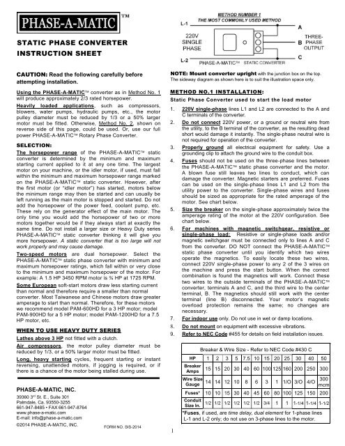
Phase o matic wiring diagram. North America Phase Converters Electrical Supply Pages 1 4 Flip Pdf Fliphtml5. How does a static phase converter work pam 3600 hdes 20 30 220 voltios phaseconverter h s single to three 3 converters motor building power electrician talk auto start rotary conversion system magnetic frequency tripler as wiring diagram practical machinist largest electrical supply pdf an option on matic powering ... 31 Phase O Matic Wiring Diagram Wiring Diagram List. Save Image. ICE O MATIC ICEU070 SERVICE & PARTS MANUAL Pdf Download . Save Image. Ice o matic ICEU060 Manuals. Save Image. New Wiring Diagram Ice Maker #diagrams #digramssample # Save Image. ICE0806FA Ice O Matic Air Cooled mercial Full Cube Ice . The wiring diagram service provides the wiring diagrams for our products according to: Order/Commission no. in PDF format. The wiring diagram opens in a pop-up window. If the pop-up blocker is turned on in your browser, you are not able to view the wiring diagram. Please enter the address of our website in the "Address of Web site to allow" box ... PHASE-A-MATIC, INC. 39360 3rd St. E., Suite 301 Palmdale, Ca. 93550-3255 661-947-8485 • FAX 661-947-8764 www.phase-a-matic.com E-mail: info@phase-a-matic.com ©2012 PHASE-A-MATIC, INC. NOTE: Mount converter upright with the junction box on the top. The sideway diagram as shown here is to suit the illustration space only. 2
Nov 30, 2017 · Phase A Matic Static Converter Wiring Diagram. Static converters on phase a matic inc model pam 200hd 3 4 to 1 2 hp heavy duty converter how does work napcco item r 10 rotary by wiring diagrams quest practical machinist largest manufacturing technology forum the web caution read following carefully before attempting installation 900hd 289 33 8 ... Phase O Matic Wiring Diagram – One of the most difficult automotive repair tasks that a mechanic or repair shop can acknowledge is the wiring, or rewiring of a car’s electrical system.The misfortune in fact is that every car is different. in the same way as infuriating to remove, replace or fix the wiring in an automobile, having an accurate and detailed Phase O Matic Wiring Diagram is ... Phase-O-Matic. Work out the size you need: Estimate the size you need by following these three easy steps: 1. List all motors on the system by size and type of use. 2. Add up the horse power rating of each motor to get the total system horse power. 3. Find the model on the chart that correlates to the total system horse power and largest motor ... Phase O Matic Wiring Diagram. Assortment of phase o matic wiring diagram. A wiring diagram is a simplified standard photographic representation of an electrical circuit. It shows the components of the circuit as simplified shapes, and the power as well as signal links in between the devices. A wiring diagram generally gives info about the…
Most older three-phase machines had no "heater" in the B-phase anyway. This is not true today. Such a converter would be connected directly to the motor's T1, T2 and T3 leads, where. T1 = A = L1, and. T3 = C = L2, and. the third wire of the converter is connected to T2 = B, with the T2/B wire to the starter having been disconnected. On two phase grinders, in ... Turn this to right under wiring installation instructions. Prongs are tripped by table dogs for table reversing. ... (Power Feed Model Only) D S6I8L-25 18" Hose Assembly—5/16B64I O.D6 . 1 4 Drip Line to Clutch (Power Feed) E S6I8L- 7 18" Hose Assembly—7/1B3I36 O.D. 1 ... Phase A Matic Pam 300hd Wiring Diagram - wiring diagram is a simplified adequate pictorial representation of an electrical circuit.It shows the components of the circuit as simplified shapes, and the aptitude and signal associates in the midst of the devices. About Press Copyright Contact us Creators Advertise Developers Terms Privacy Policy & Safety How YouTube works Test new features Press Copyright Contact us Creators ...
We continue to hear of our Rotary Converters that have been in service for 25 or 30 years, and which are still working flawlessly. It could go on to do another 25 or 30 years. There is very little to go wrong with the Rotary Converter. Call Phase-A-Matic™, Inc. 1-800-962-6976 for warranty repair stations in your area.
Phase-O-Matic. Work out the size you need: Estimate the size you need by following these three easy steps: 1. List all motors on the system by size and type of use. 2. Add up the horse power rating of each motor to get the total system horse power. 3. Find the model on the chart that correlates to the total system horse power and largest motor ...
Phase-A-Matic, Inc., with a full line of quality rotary phase converters, static phase converters, voltage stabilizers, and transformers, can assist with determining which converter and size best suits your applications and needs. Email: info@phase-a-matic.com Phone: 800-962-6976. Become a Dealer Where To Order .
a) 120 volts ac for two wire 120 volt models. b) 220 volts ac for two wire 220 volt models. 4. Disconnect the brewer from the power source. If voltage is present as described, proceed to #5. Ifv otal gesi n otp resenta sd escribed r, efert o thew rini g diagrams and check the brewer wiring harness. 5. Locate the blue/black wire on the control ther-
NOTE - Bunn-O-Matic recommends 1/4" copper tub-. Installs, repairs and maintains, in accordance with diagrams, Installs electrical conduit, wiring, switching devices, controls, motors and other.
Wiring Diagrams, Appendix "E". Note: These wiring diagrams are for reference only and should not be used in place of wiring diagrams for a specific switch.) All phases of the preferred power source are continuously monitored by a voltage sensitive relay which is adjustable from 70% to 90% of the nominal voltage.

Jual Inverter Ls M100 Pengganti Inverter Ls Ic5 0 75kw 1hp 1phase 220v Di Lapak Inverter Plc Servo Bukalapak
A 10 HP Phase Perfect digital phase converter can handle a 7.5 HP machine and is only a little more expensive than than the 15 HP rotary you could need for 7.5 HP. Below are prices of Phase-A-Matic rotary phase converters:
1. Wire the PHASE-A-MATIC static phase converter to the idler motor as described in Method No. 1, side 1. 2. Size fuses and wires on the single-phase side as appropriate for the motor’s rated amperage. Once running, the idler motor can then power the load motor. Wire the load motor in parallel to the idler motor as per Method 2 diagram No. below.

Schematic Wiring Diagram Hw2 Schematic Wiring Diagram Hw2a Wiring Diagrams Bunn Hw2 User Manual Page 4 4 Original Mode
View all of our static phase converter products here: https://temcoindustrial.com/shop/phase-converters/static-phase-convertersView our full line of Motor St...
SZCY LLC AC 220V/2.2KW Variable Frequency Drive, 12A VFD Inverter Frequency Converter for Spindle Motor Speed Control (Single-Phase Input, 3 Phase Output) 4.5 out of 5 stars 207 1 offer from $91.59
Phase O Matic Wiring Diagram – wiring diagram is a simplified within acceptable limits pictorial representation of an electrical circuit.It shows the components of the circuit as simplified shapes, and the power and signal connections along with the devices.
Phase O Matic Wiring Diagram Free Wiring Diagram. Save Image. Wiring Diagrams Factory I O Documentation. Save Image. A.o.smith Motors Wiring Diagram Cadician's Blog. Save Image. Rickenbacker 620 Wiring Diagram plete Wiring Schemas. Save Image. pact Photoelectric Sensor CX 400 Ver.2 I O Circuit and .
Phase-A-Matic Static Phase Converter Installation regarding 3 Phase Converter Wiring Diagram by admin From the thousands of photographs on the net in relation to 3 phase converter wiring diagram, we all picks the best choices along with best quality exclusively for you all, and now this photographs is usually one among photographs choices in our ideal pictures gallery about 3 Phase Converter ...
Wire the PHASE-A-MATIC static phase converter to the idler motor as described in Method No. 1, side 1. 2. Size fuses and wires on the single-phase side as appropriate for the motor’s rated amperage. Once running, the idler motor can then power the load motor. Wire the load motor in parallel to the idler motor as per Method No. 2 diagram below.
Phase-A-Matic, Inc. is a leading supplier of Phase Converters, Voltage Stabilizers, and Transformers for every industry including: restaurant, clothing, marine & nautical, HVAC refrigeration, hotel, medical, automotive, CNC, metal & woodworking fabrication, agriculture, welding, and a host of other home shop and commercial applications.
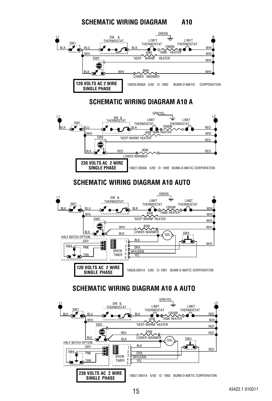
Schematic Wiring Diagram A10 A Schematic Wiring Diagram A10 A Auto Schematic Wiring Diagram A10 Bunn 10 Cup Pourover Coffee Brewer A10 User Manual Page 15 15 Original Mode

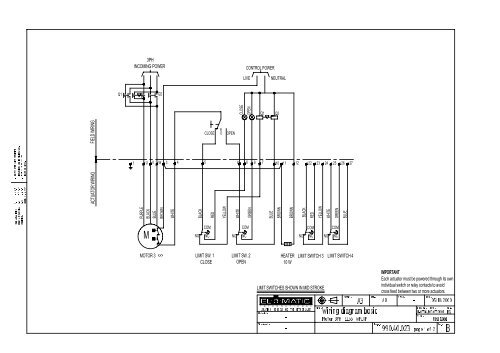






0 Response to "35 phase o matic wiring diagram"
Post a Comment