40 steam boiler piping diagram
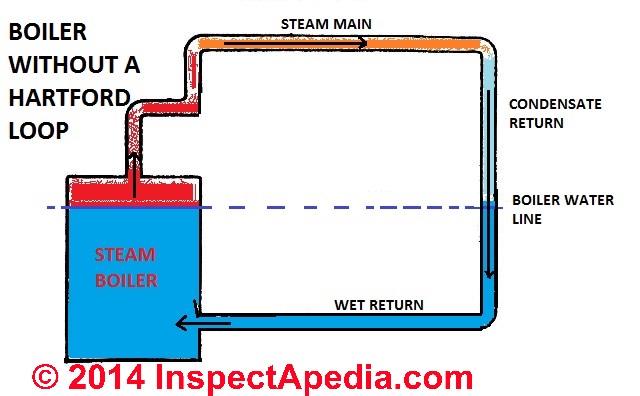
Steam Piping Best Practices - CleanBoiler.org The correct way to install a PRV is shown in the above diagram. There must be a minimum distance between the PRV and sensing point, and the control line must slope down to the pipe - NOT the PRV, so that condensate will drain back to the steam line where it will be removed by a steam trap. steam boiler piping diagram - Industrial Autoclave ... Piping Diagram - Cemline. CEMLINE® has made a series of typical piping arrangements for the Model Series: USG High Temperature Hot Water Fired Steam Generator - PDF or DWG. A Hartford Loop is an arrangement of piping between a steam boiler's header and its gravity-return piping. The end of the header drops vertically below the.
PDF Design of Boilers Piping - National Board of Boiler and ... Design of Boilers and Power Piping Section I PG‐58.3 Boiler External Piping • The Code Jurisdictional Limits of the boiler external piping systems are shown in Figure PG‐58.3.1. • The materials, design, fabrication, installation and testing shall be in accordance with B31.1, Power Piping.
Steam boiler piping diagram
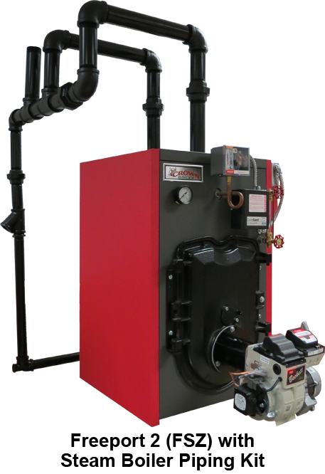
41 Steam Boiler Piping Diagram - Diagram For You Burnham Steam Boiler Piping Diagram - schematron.org Jun 10, 2018 · Burnham Steam Boiler Piping Diagram Jan 7, In October, my 30+ year old steam gas boiler was replaced (had corrosion and leaking gas) with a Burnham Independence Steam boiler. It is common and acceptable practice to install these boilers in lower pressure systems, below the ... PDF Steam Near Boiler Piping Kits - PB Heat: Peerless® Boilers All near boiler piping including Hartford loop connections Part Number Steam Boiler Model Numbers 63910 63-03L & 63-03 63911 63-04L & 63-04 63912 63-05L Through 64-07 Now Available! Near Boiler Piping Kits for Peerless® Series 63/64™ Gas-Fired Steam Boilers. Save time and money with one complete piping kit. Kits contain PDF STEAM BOILERS - Slantfin VENT PIPING— A. Vent piping installation must be in accordance with ANSI Z223.1-latest edition, National Fuel Gas Code, Part 7, Venting of Equipment. Other local codes may also apply and must be followed. B. Boiler vent pipe must be the full diameter of the boiler draft hood outlet. See dimensions, page 2. If a vent damper is
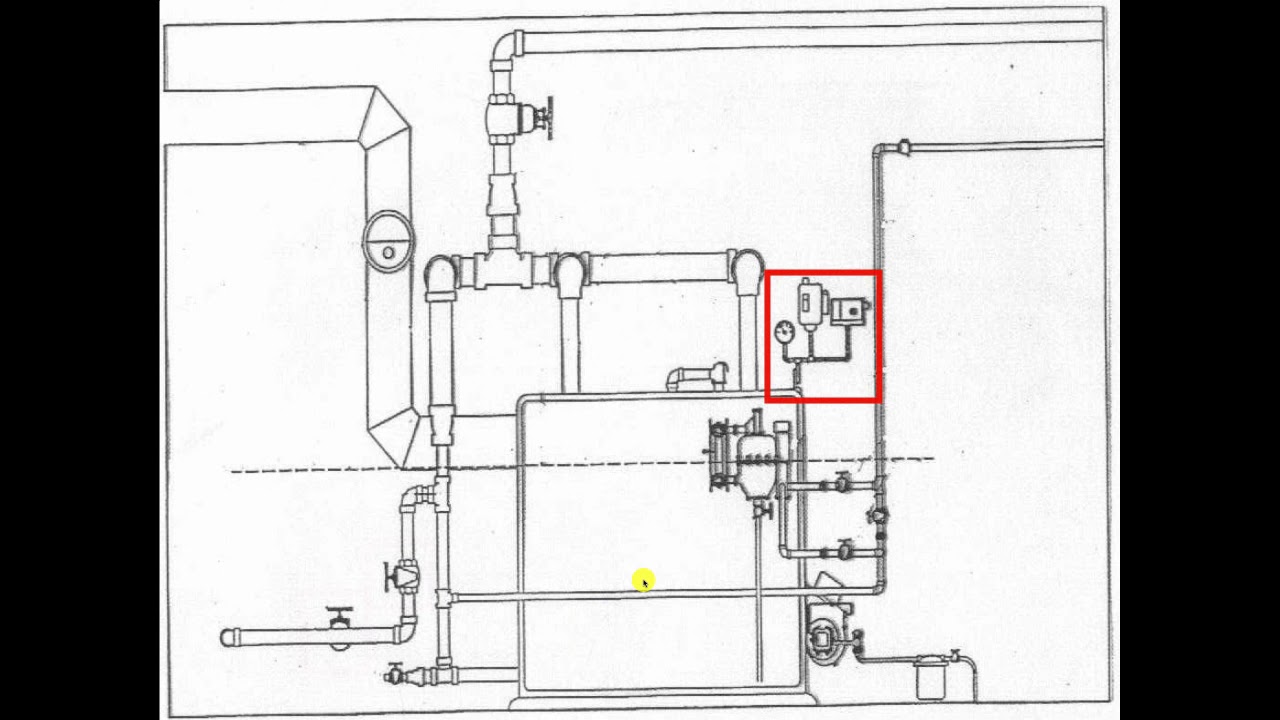
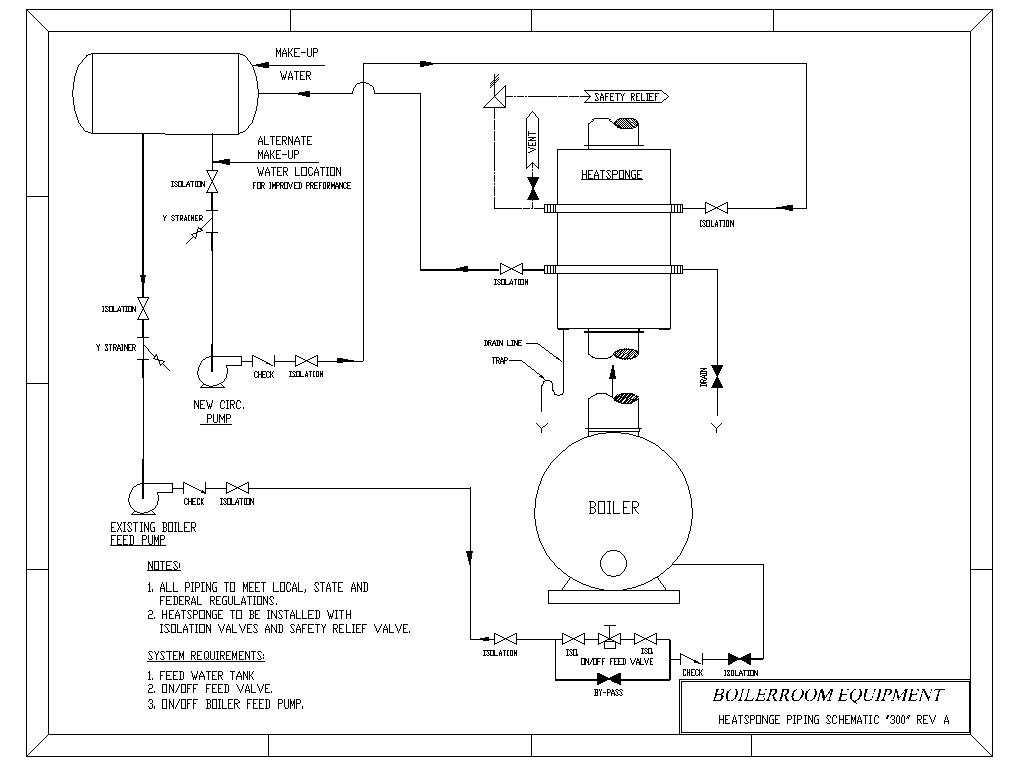
Steam boiler piping diagram. Steam Boiler Diagram With Parts for Dummy's Below is a typical steam boiler diagram for dummy's to understand with name of each component or boiler part. First of all you should understand that there are many types and nomenclature of boilers. For example steam boiler, combi boiler, vaillant boiler, hot water boiler, gas boiler, electric boiler, weil mclain boiler, condensing boiler, oil boiler, burnham boilers, central boiler ... PDF Multiple Boiler Piping Diagram - Lochinvar, LLC multiple boiler - primary/secondary piping crest . from system relief valve hot water generator water generator circulator boiler drain (typical) boiler pump (typical) ball valve (typical) air seperator drain port (typical) system circulator to system make up water back flow preventer pressure reducing valve pressure PDF INSTALLATION AND OPERATION MANUAL - BoilerData.com the discharge pipe between such valve and the atmosphere. Doing so can cause an accidental explosion from overpressure. The discharge from the safety relief valve shall be so arranged that there will be no danger of scalding personnel or damage to equipment. Provisions should be made to properly drain safety relief valve discharge piping. Steam Boiler Piping Diagrams Piping Diagrams - HeatSponge. Steam Boiler: HeatSponge Diagram 300-Rev A: This is a piping diagram for using a circulator pump to circulate water fram a tank, through the HeatSponge, and . Steam Boiler Piping Diagram — Heating Help: The Wall. the steam main leaves the boiler's header. So it wouldn't be shown on that Columbia/Utica gas steamer ...
How NOT to Design a Steam System Many Steam boilers are undersized for the actual ... Add losses for the piping, distribution, etc. ... Must account for the Lower Boiler Steam Flow at.44 pages PDF I. Piping Diagrams 13. Wire the tank or system/pipe sensor connected to the DHW sensor terminals on the follower boiler addressed as #1. 14. The system/pipe sensor must be placed on common piping to the tank, as close to the tank as possible. 15. The system/pipe sensor is wired to the system sensor terminals on the master boiler. Steam System Design and Best Practices Related to Kiln Drying Steam Boiler – high or low pressure ... Proper layout design & pipe sizing of mains ... condensate collection points (low spots) in piping.127 pages Boiler Manuals and Wiring Diagrams for Columbia Boiler Co ... WIRING DIAGRAMS. Most of the wiring diagrams are for natural gas powered steam boilers. Wiring diagrams for oil burning and water boilers are noted. CT 6, 10, 15 and 25 boiler wiring diagram. CT 6 and 25 boiler wiring diagram. CT 35 and 50 boiler wiring diagram. HRT 20 and 30 boiler wiring diagram. Keystone series boiler wiring diagram.
Steam Boiler Piping Diagram - Heating Help: The Wall Steam Boiler Piping Diagram. Steamhead Member Posts: 15,178. September 2005. in THE MAIN WALL. the "one-pipe" or "two-pipe" parts of the system occur after the steam main leaves the boiler's header. So it wouldn't be shown on that Columbia/Utica gas steamer diagram. What type of boiler and system do you have? PDF Installation and Operating Service Manual - Bryan Steam piping must be the same size as the relief valve discharge opening. Avoid over-tightening as this can distort valve seats. All piping from relief valve must be independently supported with no weight carried by the valve. 1.4.5 BLOWDOWN CONNECTION Blowdown valve(s) must be full size of the connection on the boiler. Steam boilers 15 psig and Burnham Boiler Piping Diagram - wiringall.com SERIES 2 (model B) GAS BOILERS. SERIES 2 Boiler pdf manual . If you have a Burnham Boilers dealer near you stop in and ask them for a It contains detailed piping diagrams and common wiring diagrams.Jan 01, · If you have a Burnham Boilers dealer near you stop in and ask them for a little guide called "Burnham Hyrdonics Heating Helper". Steam Boiler Piping Tips - YouTube Dan Holohan explains best practices for how to pipe a steam heating boiler. Learn more at to be an expert? Read Dan Holohan's book T...
Steam Heating Systems - Design
Burnham Boiler Piping Diagram - schematron.org The expansion tank must be properly. As drawn in the diagram, to charge the tank from the primary loop. 2. tanks ( where the hot water enters) and going to the Burnham boiler. ma servicing a gas steam boiler burnham piping diagram furnace ac and plumbing repair in. burnham steam boiler gas manual. steam boiler wiring diagram.
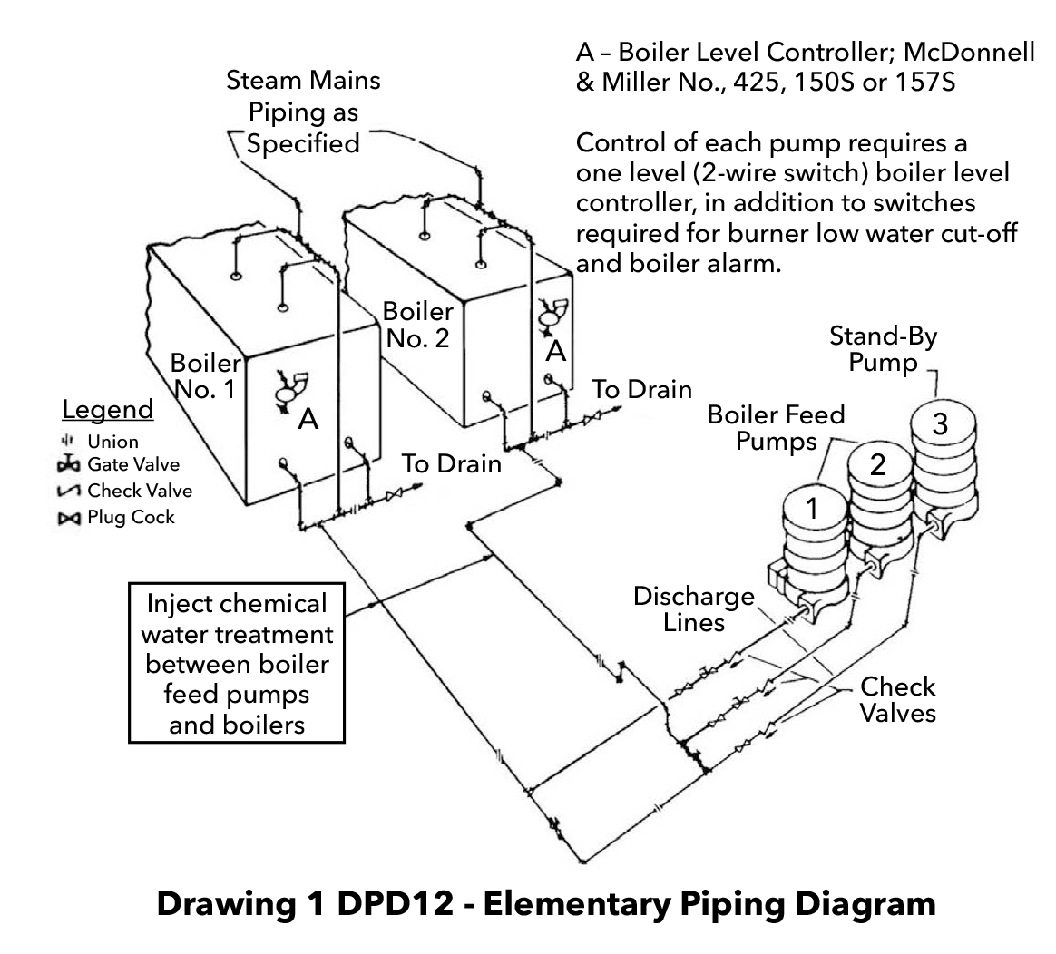
Typical boiler feed unit discharge piping arrangements ...
Standard Steam Boiler Plant Piping Diagram - Veterans Affairs Standard Steam Boiler Plant Piping Diagram Author: Department of Veterans Affairs, Office of Construction and Facilities Management, Facilities Standards Service Subject: Standard Details Created Date: 10/7/2020 2:22:24 PM

Here's a 3d model of the near boiler piping I'm planning. Any ...
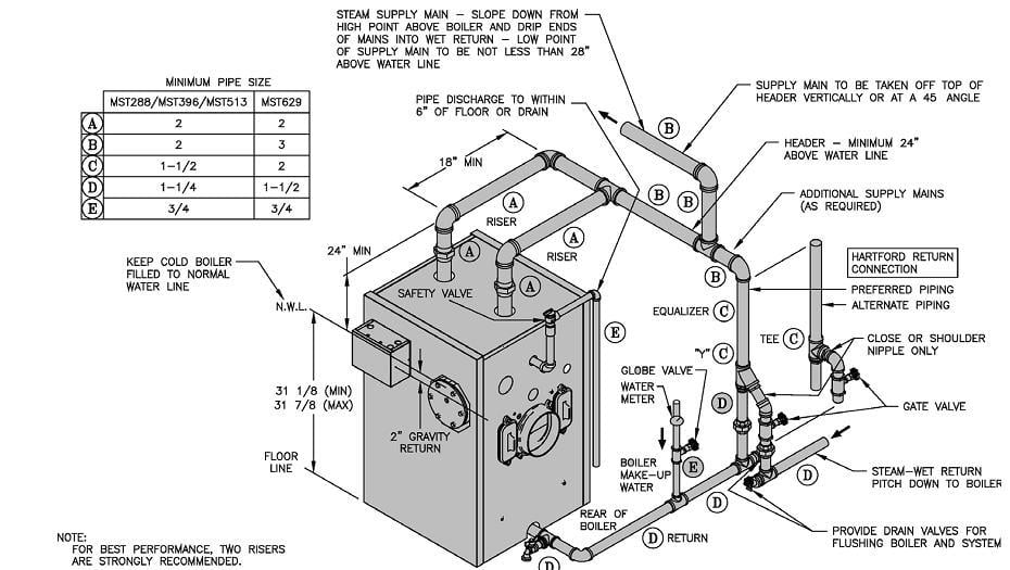
PDF Typical Piping for Conventional Single Boiler Installation ... application type diagram see installation manual for complete instructions. install in accordance with all local codes. typical piping for conventional single boiler installation lb-500, lb-750, lb-1000 • safety relief valve setting should not exceed pressure rating of any component in the system. • piping should conform to local codes.
Steam System Design and Best Practices Related to Kiln Drying
Boiler Basics Part 4 - Piping - HVAC School The piping must have pitch or fall to help the steam rise, and more importantly, to allow the condensate to flow back to the boiler. Level piping holds water, so it must have fallen. Also, a Hartford Loop is required to connect the supply and return.
Another steam boiler | Plumbing Zone - Professional Plumbers ...
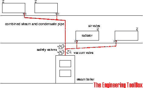
steam boiler piping diagram - Boiler Sale Both steam boilers and hot water boilers may share certain controls that monitor and Hartford loop piping schematic for a steam boiler - adapted from ITT's The. The steam piping should come off the top of the header pipe to assure that only dry steam leaves the boiler. Figure 5-6 is a schematic of a two-pipe system.

Help identifying my piping loop?... — Heating Help: The Wall
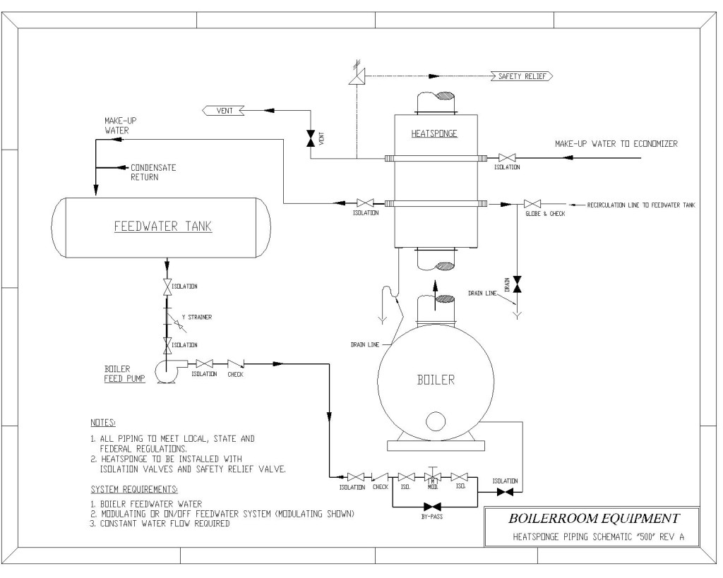
Piping Diagrams - HeatSponge Steam Boiler: HeatSponge Diagram 100-Rev A: This is a piping diagram for the typical installation where the HeatSponge is located between the boiler feedwater tank, either a deaerator or feed tank, and the boiler. Steam Boiler: HeatSponge Diagram 300-Rev A: This is a piping diagram for using a circulator pump to circulate water fram a tank ...

Vintage American Standard Boiler Replacement in Littleton
Hartford Loop Piping Diagram - wiringall.com The primary component of a Hartford loop diagram is the location of a Hartford loop top and its distance from the boiler water top. Standard Hartford loop diagrams generally place the top of the loop 2 inches below the steam boiler's water line. hartford loop steam piping diagram is among the photos we discovered on the net from reputable sources.
New gas boiler pipping help — Heating Help: The Wall
Steam Piping Systems - an overview | ScienceDirect Topics 15.9.1 Main Steam Lines. Steam lines should ideally be arranged to fall in the direction of flow, at not less than 100 mm per 10 m of pipe (1:100). This slope will ensure that gravity (and the flow of steam), will assist in moving the condensate towards drain points so that the condensate may be safely and effectively removed (see Fig. 15.4 ).

Steam Boilers Selection Guidelines
Piping Diagram - Cemline Product Drawings. Piping Diagram. Technical Papers. 3D-Drawings. Spec Sheets. CEMLINE® has made a series of typical piping arrangements for the Model Series: SEH, SSH, SWH, and USG. These drawings are in .DWG format or Adobe®Acrobat® (PDF) format. The Acrobat Reader is available free from Adobe. Note: Select the model and click on the ...

Weil-McLain 80 Connect steam boiler piping
ONE-PIPE STEAM SYSTEMS YSTEMS - Peerless® Boilers The near boiler piping is the first line of defense for a reliable system. a) Correctly installed, the near boiler piping acts as a ... Steam Boiler fires. Water boils in boiler, creating steam. Surface level rises slightly because the steam bubbles displace water.
Steam and Condensate - A basic overview of a steam system ...
Burnham Steam Boiler Piping Diagram - schematron.org Burnham Steam Boiler Piping Diagram Jan 7, In October, my 30+ year old steam gas boiler was replaced (had corrosion and leaking gas) with a Burnham Independence Steam boiler. It is common and acceptable practice to install these boilers in lower pressure systems, below the boiler MAWP. Therefore, Burnham offers safety relief valves set at or ...

Steam boiler system nodalization diagram | Download ...
Steam Boiler Piping Diagram - Heating Help Steam Boiler Piping Diagram. Sharing. Published: February 20, 2018. Categories: Steam. Steam boiler piping: The right way to pipe takeoffs from a header.
Near-Boiler Piping in Steam Heating Systems
Near-Boiler Piping in Steam Heating Systems Boilers are much smaller nowadays, so you have to consider the piping around the boiler to be part of the boiler. These newer boilers don't have the internal cathedral-like space for steam release that the old boilers had. Near-boiler piping is crucial because it's being used to slow the steam down and dry it out.
The importance of near-boiler piping in a steam system
PDF STEAM BOILERS - Slantfin VENT PIPING— A. Vent piping installation must be in accordance with ANSI Z223.1-latest edition, National Fuel Gas Code, Part 7, Venting of Equipment. Other local codes may also apply and must be followed. B. Boiler vent pipe must be the full diameter of the boiler draft hood outlet. See dimensions, page 2. If a vent damper is
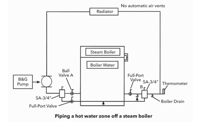
How to Run a Hot Water Zone Off a Steam Boiler | 2016-11-21 ...
PDF Steam Near Boiler Piping Kits - PB Heat: Peerless® Boilers All near boiler piping including Hartford loop connections Part Number Steam Boiler Model Numbers 63910 63-03L & 63-03 63911 63-04L & 63-04 63912 63-05L Through 64-07 Now Available! Near Boiler Piping Kits for Peerless® Series 63/64™ Gas-Fired Steam Boilers. Save time and money with one complete piping kit. Kits contain

PIPING KIT STEAM BOILER PEG225 UTICA | Behler-Young
41 Steam Boiler Piping Diagram - Diagram For You Burnham Steam Boiler Piping Diagram - schematron.org Jun 10, 2018 · Burnham Steam Boiler Piping Diagram Jan 7, In October, my 30+ year old steam gas boiler was replaced (had corrosion and leaking gas) with a Burnham Independence Steam boiler. It is common and acceptable practice to install these boilers in lower pressure systems, below the ...
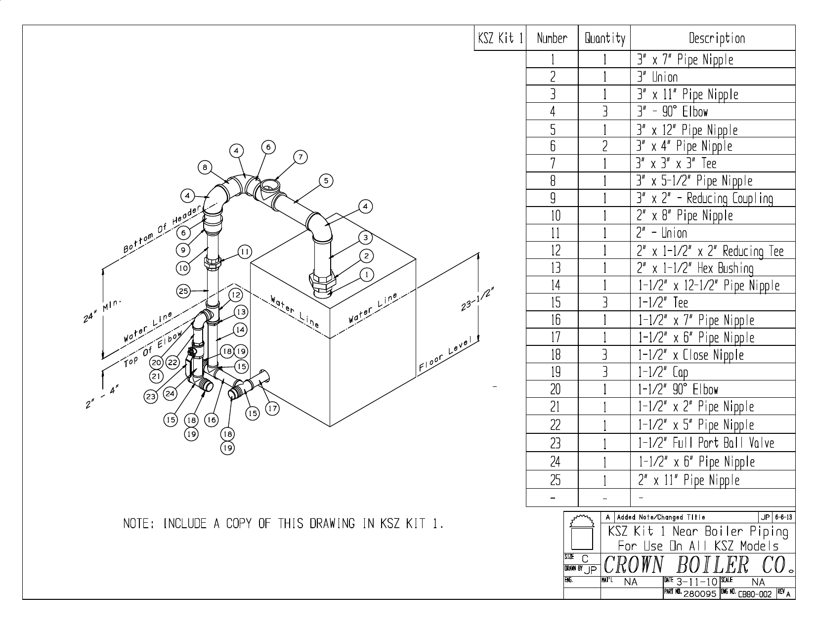
Crown Boiler Kingston Near Boiler Piping Kit Product Manual ...

Core Principles Of One-Pipe Steam Radiators | Castrads

Typical Steam Boiler Piping Diagram Click Visit And Get More ...
Steam Near Boiler Piping Kits

Understanding Steam Boiler and Its Process
STEAM / GAS APPLICATION GUIDE

Dunkirk Steam Boiler Piping Diagram - camizu.org | Steam ...
The Hartford Loop on Steam Boilers Definition, function ...
Steam Boiler Piping Kits - Velocity Boiler Works
National Oilheat Research Alliance 1

New Boiler Install - Water Hammer Issues - DoItYourself.com ...
How NOT to Design a Steam System
How NOT to Design a Steam System

HRH STEAM PIPING LAYOUT | Download Scientific Diagram
Piping Diagrams
How NOT to Design a Steam System

Underwriter's loop: a plumbing arrangement on steam boilers ...

Crown Boiler Bermuda Near Boiler Piping Kit Product Manual ...

Series 63/64™Near Boiler Piping Kit - PB Heat

Cleaning a new steam boiler installation - Slantfin

Hartford Steam Boiler Building Cafeteria Click Visit and Get ...
Modeling and simulation of a natural circulation water-tube ...
Piping Diagrams
P&ID diagram for Boiler - Industrial Automation - Industrial ...
0 Response to "40 steam boiler piping diagram"
Post a Comment