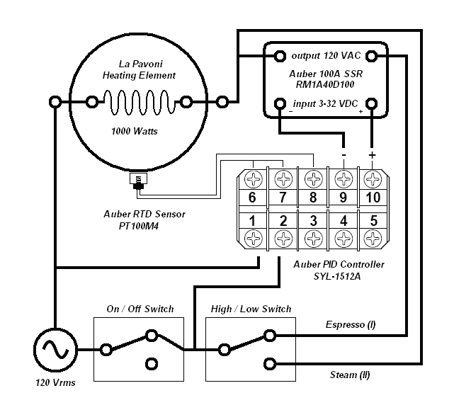
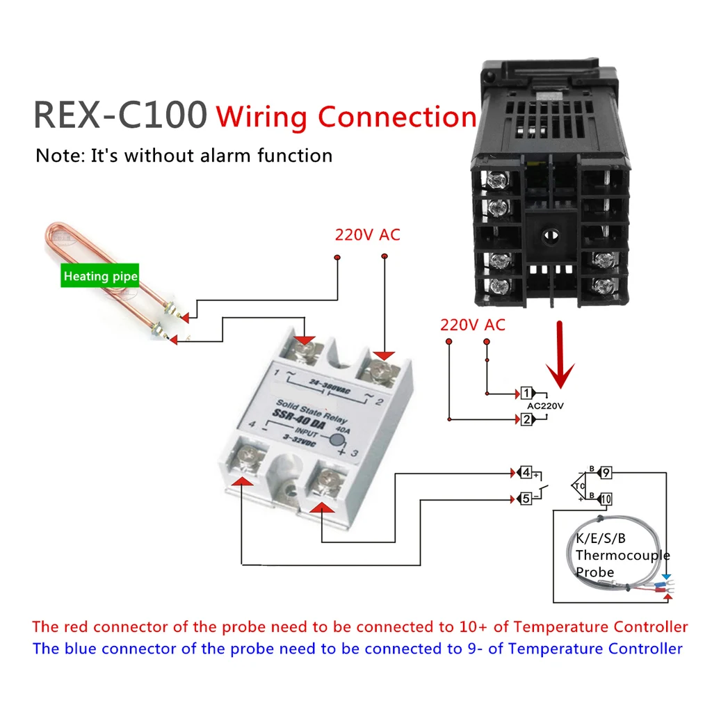
37 pid temperature controller wiring diagram
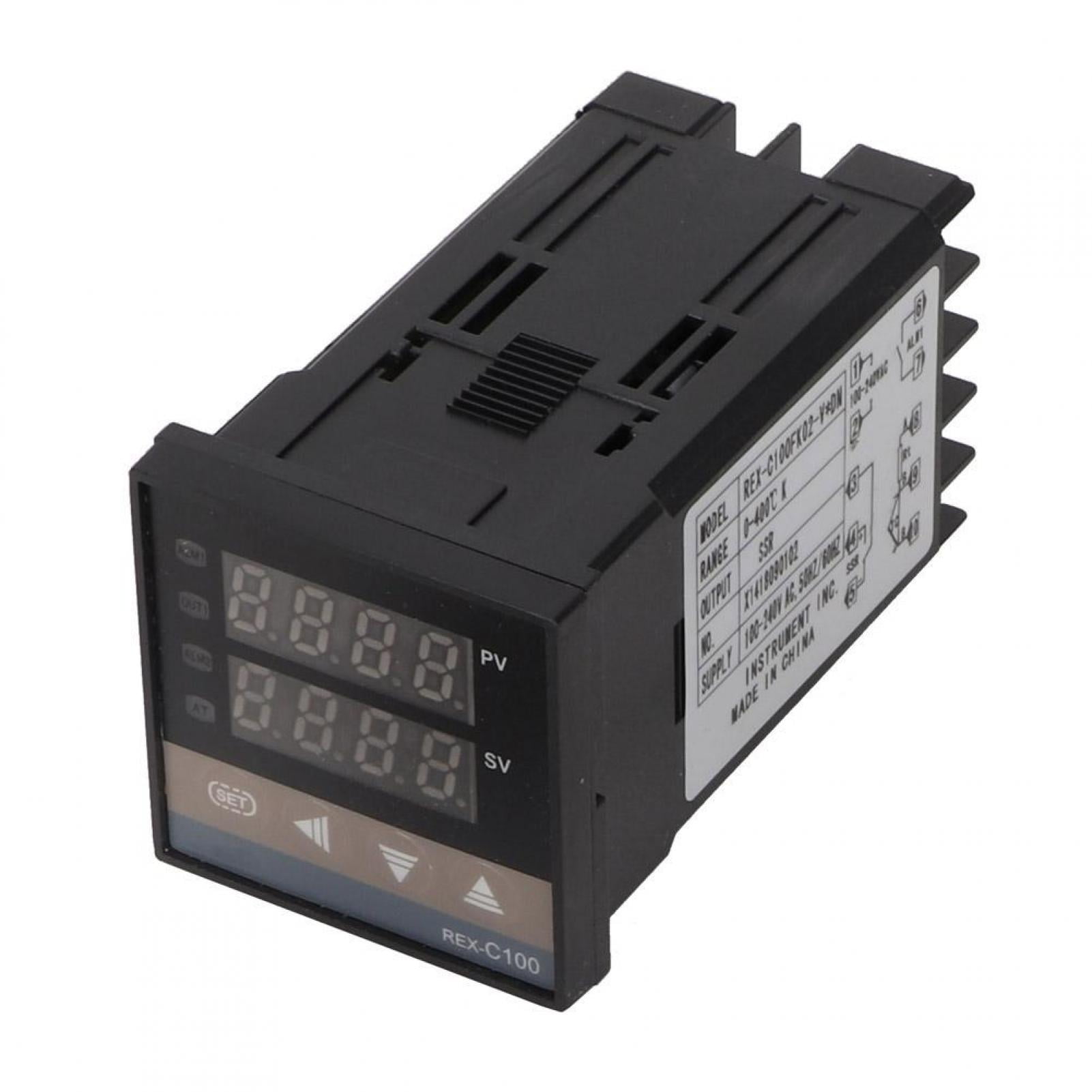
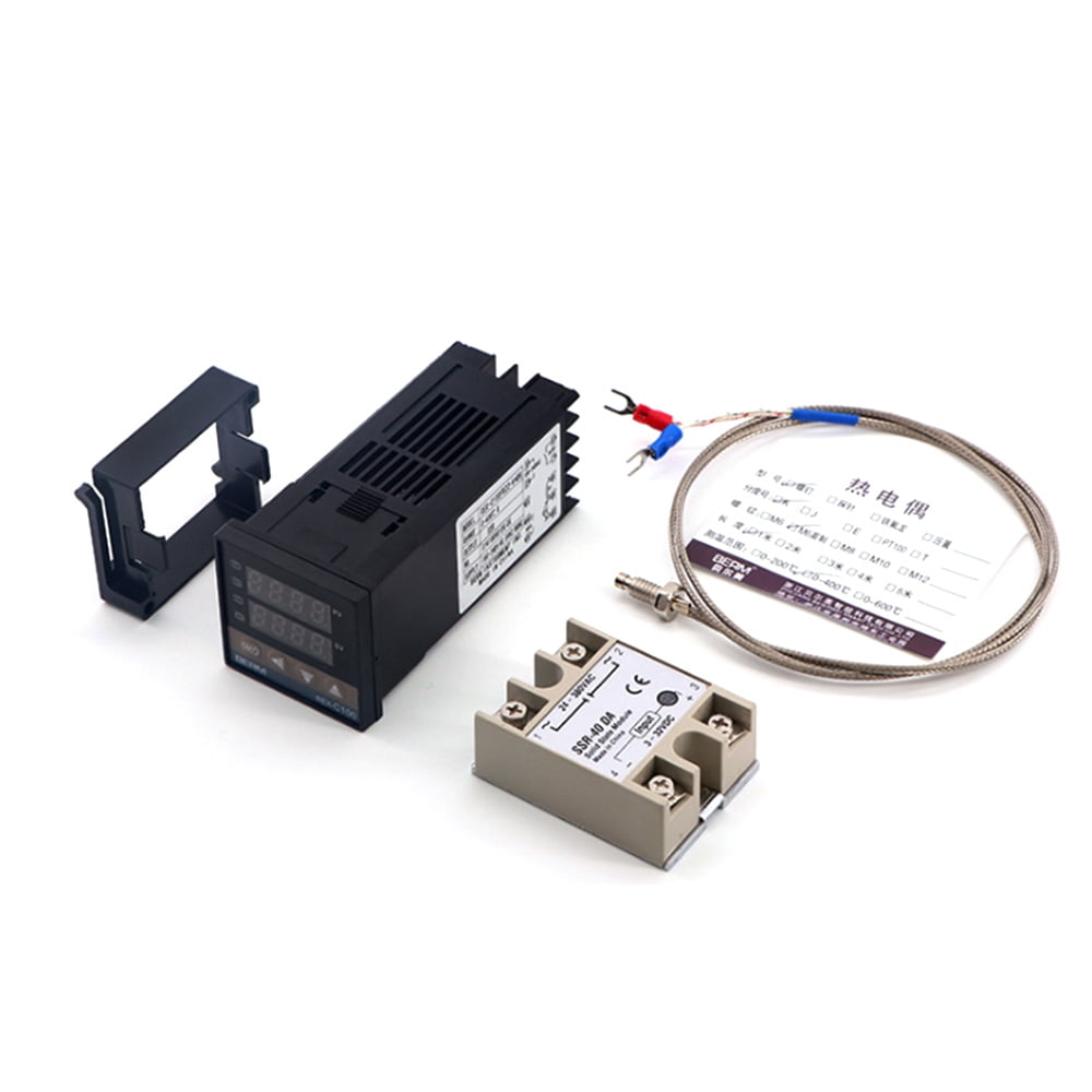
PID Kit for Beer Brewing (Temperature controller , RTD ... Dual Digital PID Temperature Controller . This Universal Intelligent Temperature Controller has a universal type thermocouple input, including Thermocouples K, J, R, S, B, E, T, N type and RTD (JPt100 or Pt100). It is an ideal solution for a wide range of professional applications to automatically control temperatures of up to 1600 °C. Pid Temperature Controller Wiring Diagram - autocardesign Pid Temperature Controller Wiring Diagram - wiring diagram is a simplified good enough pictorial representation of an electrical circuit. It shows the components of the circuit as simplified shapes, and the skill and signal contacts in the midst of the devices.
PDF gL101 user's guide golanderusa J1 relay can be set to PID or on/off control output, or can be used as an alarm relay (see . OUTY. in . Table 1). Please note the J1 relay is just a switch, there is no power on it. The power need to be provided to the load connected to the terminal 4and 5. 4.4 Power to the controller . The controller can be powered by AC/DC from 85 to 260V.

Pid temperature controller wiring diagram
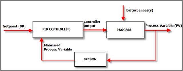
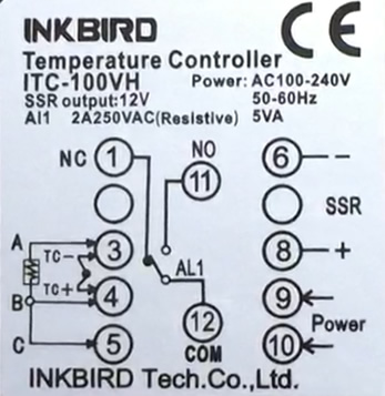
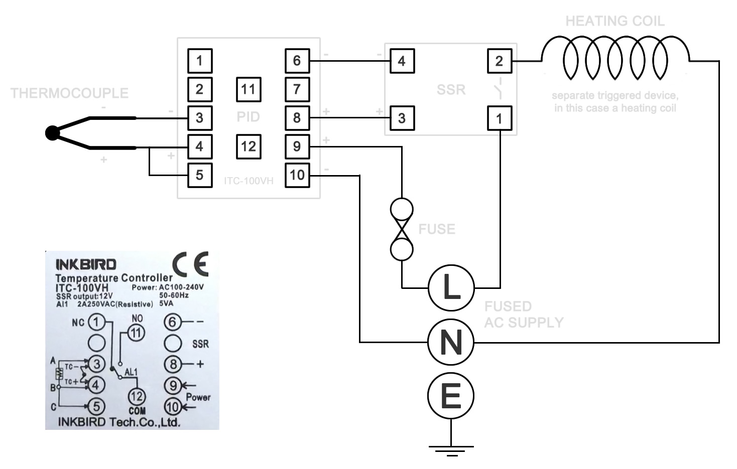
PDF BASIC PID TEMPERATURE CONTROLLER - Jameco basic pid temperature controllertc518. operating instructions tc518 48 x 48 specifications sensor - (factory set) ... the wiring arrangement. ... connection diagram : 1) for thermocouple tc+tc-6 7 8 910 thermocouple + - PID Inkbird ITC-100VH wiring usage overview Wiring & Using the Inkbird ITC-100VH PID Temperature Controller. Whilst building an electric foundry, I made use of a PID to accurately and safely control the heat. PID stands for Proportional Integral Derivative and in simple terms is a feedback mechanism. It monitors a system and then applies a specific control as and when necessary. Pid Temperature Controller Wiring Diagram - Diagram ... Posts Related to Pid Temperature Controller Wiring Diagram. Rosemount Temperature Transmitter Wiring Diagram. Mishimoto Fan Controller Wiring Diagram. Traeger Controller Wiring Diagram. 36v Electric Scooter Controller Wiring Diagram. ... Salt Dogg Spreader Controller Wiring Diagram.
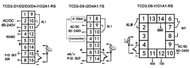
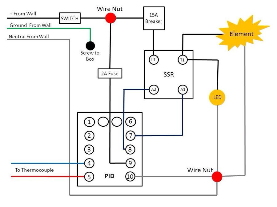
Pid temperature controller wiring diagram. How I wired a PID to control temperature - Gunloads.com 8) Mount PID controller to base. 9) Run a pair of wires from screws across from White Plug Wire and the Black Plug Wire to PID AC/DC input contacts 1 and 2 on my controller, polarity does NOT matter with AC power. 10) Run a wire from PID SSR+ (contact #6) to SSR A1+. 11) Run a wire from PID SSR- (contact #7) to SSR A2-. WIRING THE PID CONTROLLER - YouTube Visit us on face book and subscribe to this page.Please use caution when wiring your own PID controller. They can be found on google and are relatively inexp... PID Temperature Controller, Dual Digital, Universal Input ... 1. PID temperature controller wiring diagram 2. PID temperature controller with RS485/232 or transmitter wiring diagram 3. PID temperature controller with timer relay wiring diagram Tips: What is PID control in temperature controller? In temperature controller, PID control is setting parameter P to non-zero (set parameter P to zero is called ON ... PID Temperature Controller Wiring Problems - RIMS ... Wondering if anyone has run into the same problem as me with their temperature controller/heating element and could help me out. I have a N2006P PID Temp controller that I got on eBay from a company in Hong Kong. The wiring diagram they gave me is found on the last page of the pdf document...
PDF ITC-106 User Manual is no gap among the controller, panel and the adapter and then fasten the two screws on the adapter with the torque of 0.29N to 0.39N. Be sure the ambient temperature is within the stated working range in the manual, especially when there are two or more temperature controllers installed. 4. Wiring Diagram PDF Inkbird Pid Controller Wiring Diagram Inkbird Pid Controller Wiring Diagram wiring a pid temperature controller for sale climate, inkbird idt e2rh wiring 23 wiring diagram images, ssr circuit diagram pid inkbird itc 100vh wiring usage, pid temperature controller wiring diagram bagsluxumall com, pid temperature controller wiring diagram bavicodalat com, support faqs question 4 inkbird, PID controller wiring diagram, will this work OK ... Re: PID controller wiring diagram, will this work OK? the final dimensions will be 120cm x 50cm x 50cm, i only have it set up in a box to see if the pid is doing what it should, i.e. energizing the ssr until the set temp is approached. PID Temperature Controlled Oven : 13 Steps (with Pictures ... In the instruction manual for your PID and, possibly on a sticker on the case, will be a wiring diagram like the one above. If you know how to translate it, wiring everything up is quite simple. Let's start with the temperature sensor. If you are using a 3-wire sensor, then it connects to terminals 3, 4 and 5.
Digital Temperature Controller | Full Circuit Diagram With ... Fig. 2: Circuit diagram of the digital temperature controller. Port pins RD0 through RD7 of IC1 are connected to pins D0 though D7 of the LCD. Port pins RB0 through RB2 are connected to register select RS, read/write R/W and enable EN of the LCD. ADC channel RA0 of the microcontroller receives the analogue signal from thermocouple amplifier IC2. PDF Temperature Process Control - Omega Engineering Based Temperature Process Control Specifications - Installation and Operating Instructions ... wire the controller per the appropriate wiring diagram listed on page 6. PANEL CUTOUT DIMENSIONS CN730 CN710 ... the Control Mode, the PID parameters can be accessed in the Regulation PDF N2006P PID TEMPERATURE CONTROLLER The Installation ... N2006P PID TEMPERATURE CONTROLLER The Installation & Wiring Diagrams Input type can be RTD input (Pt100, Cu50) or thermocouple input (T, R, J, B, S, K, E and Time proportioning output can be relay contact output or voltage pulse output Two alarm outputs can perform double - limit alarm or three - position control Pid Temperature Controller Wiring Diagram - Free Wiring ... Size: 216.55 KB. Dimension: 906 x 1416. Collection of pid temperature controller wiring diagram. Click on the image to enlarge, and then save it to your computer by right clicking on the image. 25 New Pid Controller Circuit Diagram The PID Part 1 Nuts Volts. Pid Diagram Newest Arduino Pid Temperature Controller Free Diagram.

DO NOT USE THIS! | HOW TO WIRE PID CONTROLLER | Pls check out the Updated Version in the Description
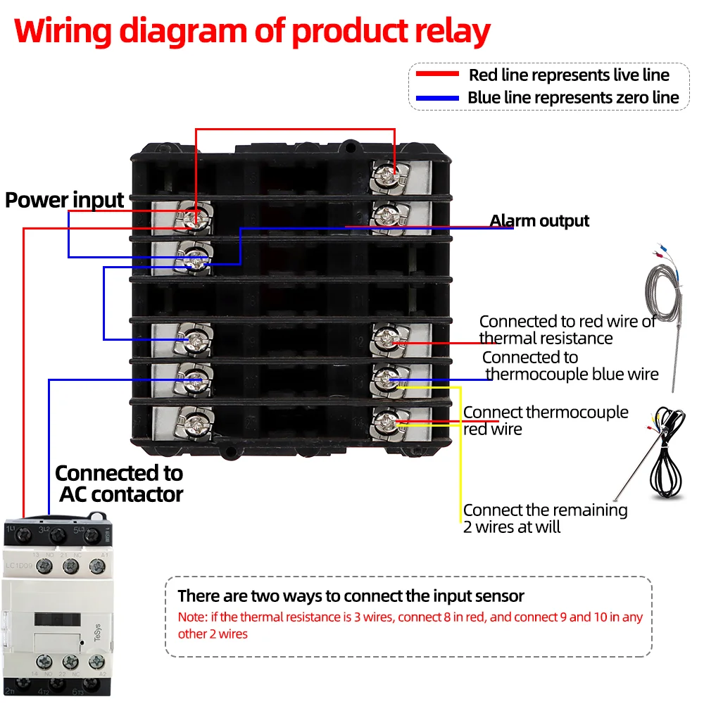
How to Connect and Set PID Temperature. Controller? ITC ... Attention:1.Important: Dual lines PT100 Sensor #3 and #4 terminals are the input ports for dual lines PT100 sensor, and #4 and #5 terminals should be connect...
PDF PID Temperature Controller - RS Components PID Temperature Controller RS Stock No. 340-083. ... others it will cause a response similar to curve A in the previous diagram. Proportional (P) control. It is possible for the controller to apply a variable amount of power to a process. This is achieved by cycling the relay output on and off for a variable percentage of a ... Full PID control ...
Building an Electric Brewing Controller - The Electric ... The brewing controller does not control the element directly. The PID is a low voltage device, while the the heater runs of 120V and draws over 18A of current. ... Wiring Diagram. ... From there the live and neutral connections go to power the temperature controller, the pump outlet and the SSR driving the element. ...
PDF Pid Temperature Controllers 3116 and 3216 Temperature Controllers Engineering Handbook Part No HA027986 Issue 2.0 May-04 1-5 1. Installation and Basic Operation 1.1 What Instrument Do I Have? Thank you for choosing this Temperature Controller. This Chapter takes you through step by step instructions to help you to install, wire, configure and use the controller.
PDF ITC-100 PID Temperature Controller User Manual After that, fix the temperature controller with attached two bolts of the fixer under torque of 0.29N to 0.39N. 3.2 Make sure the surrounding temperature is within the stipulated temperature range, especially when there are two or more temperature controllers. AC/DC 12-24V 3.Diagram and installing size (unit: mm) Figure 3: Panel Cutout
Pid Controller Schematic - Gunloads.com Pid Controller Schematic. Here is a design schematic for a PID controller for use either electric lead pot or lubersizer. If you do not stand for something, you stand for nothing. You can't spell "restore" with h-y-p-o-c-r-i-s-y. The further a society drifts from the truth, the more it will hate those that speak it. 01-27-2013, 01:20 PM #2.
PID Temperature Controller - Inkbird IPB-26. $599.00. 30A PID Temperature Controller. IPB-26. INKBIRD IPB-26 is a dedicated homebrew temperature controller with heating and water pump functions, a highly accurate temperature sensor and great heat dissipation and etc. It has been popular among homebrew fans and helping endless homebrew fans brew vintage wine...
PDF Process PID Controllers - Extech Instruments Wire a 2-, 3-, or 4-wire RTD as shown in the diagrams below. 4.6 Control Relay Wiring A basic VFL controller includes one control relay (OUT 1), the second control output (OUT 2) is optional. Control relay outputs are single-pole, single-throw (normally open N.O.) mechanical switches.
Temperature Controller Wiring - evaporative swamp cooler ... Digital Temperature Controller Wiring, Wiring Diagram For Temperature Controller, Lm35d Temperature Sensor To 92 Electrodragon, Holybro Pixhawk 4 Px4 Fc Autopilot With Pm07 Gps, Pid Temperature Controller Wiring Diagram, Media.wcyb.com is an open platform for users to share their favorite wallpapers, By downloading this wallpaper, you agree to ...
MyPin TA6 PID controller settings/wiring help | Homebrew ... "3.4 For first time users without priorexperience with PID controllers, the following notes may prevent you from making common mistakes. 3 . 4 . 1 Power to the h ea t e r does not flow through terminal 9 and 1 0 of the controller. The controller consumes less than 2 watts of power. It only provides a control signal to the relay.
Build a PID for constant bullet casting lead temperature ... (1) PID Temperature controller, DIN, SSR Control Output, #SYL-2352 = $44.50 (1) Solid State Relay SSR, # RS1A40D25 = $15 (1) Aluminum project box, #CPTbox16 = $22.32 (1) K type High Temp Probe #WRNK-191 = $21.62. All prices as of June 2011. The project box comes with the hole already cut to receive the PID control unit.
Mypin Ta4 Wiring Diagram - schematron.org to get Book file PDF Td4 Snr Ssr Controller Wiring Diagram. MyPin TA4 SNR Controller for UDS. November 28th, - MyPin TA4 SNR. The MYPIN TA4 is a PID temperature control device similar to the Here is the pin out schematic for the wiring of the screw terminals on the.Jun 09, · All of the wiring diagrams I've seen for v are wired similar to this, they just include an 'E-Stop'.
Pid Temperature Controller Wiring Diagram - Diagram ... Posts Related to Pid Temperature Controller Wiring Diagram. Rosemount Temperature Transmitter Wiring Diagram. Mishimoto Fan Controller Wiring Diagram. Traeger Controller Wiring Diagram. 36v Electric Scooter Controller Wiring Diagram. ... Salt Dogg Spreader Controller Wiring Diagram.
PID Inkbird ITC-100VH wiring usage overview Wiring & Using the Inkbird ITC-100VH PID Temperature Controller. Whilst building an electric foundry, I made use of a PID to accurately and safely control the heat. PID stands for Proportional Integral Derivative and in simple terms is a feedback mechanism. It monitors a system and then applies a specific control as and when necessary.
PDF BASIC PID TEMPERATURE CONTROLLER - Jameco basic pid temperature controllertc518. operating instructions tc518 48 x 48 specifications sensor - (factory set) ... the wiring arrangement. ... connection diagram : 1) for thermocouple tc+tc-6 7 8 910 thermocouple + -














0 Response to "37 pid temperature controller wiring diagram"
Post a Comment