36 boat tachometer wiring diagram
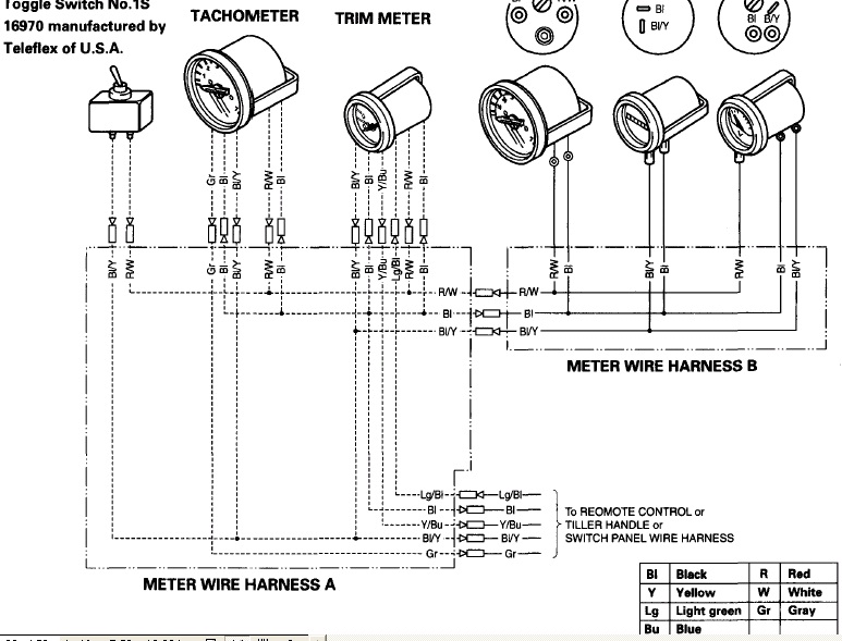
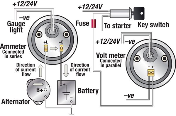
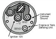
Engine Instrument Wiring Made Easy - Boats.com Those who don't will provide alternative wiring color codes on a wiring diagram associated with the engine versus the whole boat. Figure 1. Tachometer terminals. ... "G" terminal is the instrument ground and will be either black or yellow in color depending upon the vintage of the boat. Finally, the tachometer sending or "PUL" wire ... Rpm Tachometer Wiring Diagram - Studying Diagrams On Iztoss Tach Wiring Diagram. Rpm tachometer wiring diagram. Tachometer 561 hourmeter 0-3000 RPM Electrical 12 24 volts Diagram D Proper wiring of the tachometer with. This sensor is avail-able from your auto parts dealer. To install the light bulbs use needle nose pliers to insert the bulb in the bulb receptacle on back of gauge then twist ...
How To Wire A Boat | Beginners Guide With Diagrams | New ... 5. Install Terminal Block as Breakout Point. If you get your boat's switch panel fully wired ( more on that here ), then you'll have an easy to install wiring harness coming off pre-installed with heat shrink labels, and ring terminals. This is meant to land on a terminal block like this one.
Boat tachometer wiring diagram
Installation Instructions Outboard Tachometer Outboard ... 5. Insert a wire with appropriate contact to the Tachometer Signal function of the connector. Connect the opposite end to the terminal or wire originating from the unrectified side of the alternator. On most late model outboards, a tachometer hookup wire can be found at the control box. Tachometer plug-in harnesses are sometimes available INSTALLATION INSTRUCTIONS Tachometer Kit - Crowley Marine Installation. Disconnect battery cables to help prevent arcing or damage to equipment. Select a tachometer mounting location that is in full view of the operator. Drill a 3-3/8 in. (86mm) hole in the dashboard. Mount the tachometer so water will not collect on the face, or drip on the case and wires. Volvo Penta Tachometer Wiring Diagram - IOT Wiring Diagram Wiring Loom Volvo Penta 828646 Delux Panel With Gauges. Component Location Of Volvo Tad734ge Engine. Mdi Instrument Panel Volvo Penta 21180574. Volvo Wiring Diagram Disappointment Nay Anger Sailnet Community. 21628160 Volvo Penta Evc Tachometer 4000rpm. Volvo Penta Tachometer 23715875 Was 873992 And 23715874 873998 Replaces Vp873688 Vp873660.
Boat tachometer wiring diagram. gruppopdconsiglioregionalelazio.it 28.2.2022 · Does anyone have the wiring diagram for a Harbor Freight Pull Start For Harbor Freight Predator 68529 6500W 13hp 420cc Generator NOTE: Check the appearance, size, shape of this item in our picture and compare with your original one before buying. Throughout the tests, information was This is the AK-47 of boat engines. Wiring Diagram For Two Gas Engine Tachometers And A ... Smart Actuator II™ Control System Wiring Diagram - Remote Enable Switch . such as Volvo Diesel or any gasoline engine, a mechanical tachometer. The Faria Marine Instrument Bracket Mount Dual Engine. Synchronizer is case of outboard engines). Like a tachometer, the Synchronizer counts "pulses" from. The two most critical parts of the EEC ... Boat Building Standards | Basic Electricity | Wiring Your Boat A question often asked on boating and boat building forums, and by visitors to my web site, is: “I need a simple wiring diagram for a small outboard boat to wire up the lights and few other things, but no one seems to have one. How to Troubleshoot a Boat Tachometer | Our Pastimes Connect the black tachometer wire to the black ground wire. Connect the yellow wire to your lighting wiring. Connect the remaining wire (usually green) from the tach to the wiring for the engine per your boat's wiring scheme. Label each wire with masking tape and a permanent marker. Turn the tachometer over gently so that the backside is ...
Ignition Switch Wiring Diagram Chevy | Fuse Box And Wiring ... 4.1.2016 · ignition switch wiring diagram chevy - thanks for visiting my site, this message will certainly review regarding ignition switch wiring diagram chevy. We have actually collected many images, ideally this picture serves for you, and help you in locating the response you are looking for. Description : Gm Hei Wiring Pin How to install a tachometer in a boat - Marine Engine In this video I install a tachometer in my boat. I wire up the power and then select the number of pulses or cycles my outboard has to get the correct reading. Go. important_devices: ... The instructions say to use at least 18 gauge wire and this particular wire is a tinned marine wire. These are the lugs I'm going to crimp on they're about the ... EOF Tachometer Wiring Diagram - Wiring Diagram Vdo Marine Tachometer Wiring Diagram - Data Wiring Diagram Schematic - Tachometer Wiring Diagram Wiring Diagram contains several detailed illustrations that present the relationship of varied things. It consists of guidelines and diagrams for various types of wiring techniques as well as other items like lights, home windows, etc.
VDO Documentation - VDO Marine Gauges ViewLine 52mm Wiring Diagram (2014) Viewline Level Gauges 12/24 Volt (2011) Viewline Level Gauges 52mm (2008) ... ViewLine Marine Tachometer (2014) Voltage Resistance Chart (2004) Voyager Cluster Wiring Schematic (2005) Show all articles ( 16 ) Collapse Articles. Turbo. ABYC Cable & Wire Color Codes for Boat & Marine Wiring The proper wiring color codes used in the boat wiring is a best strategy for different wires tracing, time-saving, easy maintenance & troubleshooting. The DIY wiring in the boat instead of a licensed technician makes a lot of trouble as it is a painful task to figure out the desired wire in the confined space and concealed areas where a bunch of wires are laid with other bundled wire. Faria Tachometer Wiring Diagram View wiring diagrams and schematics for hundreds of popular boats including Lowe, Larson. If you have determined that the Faria Gateway box is defective, there is no direct replacement for Insert PP tach wire in the 2way connector supplied with the new Check for proper locations of gauge's ring terminals according to schematic. IS, A, FB-Sentry ... How to Wire a Boat Tachometer | Gone Outdoors | Your ... Silver core solder. Disconnect the boat's battery. Strip 1/2-inch of insulation from both ends of all the wires. Use a pliers-type crimper to crimp ring connectors to both ends of the one of the red wires and the black wire and one end of each of the gray wires. Crimp a female blade disconnect onto one end of the remaining red wire and a ring ...
Universal Diesel Engine - Wiring Harness Upgrade - Marine How To
Marine Engine Synchronizer - Glendinning Controls The Glendinning Automatic Synchronizer has been the industry standard for automatic engine synchronization for over 30 years. Engine synchronization is vital on twin engine boats, not only for the purpose of increased efficiency, but also to eliminate the annoying noise and vibration cause by engines operating at different speeds.
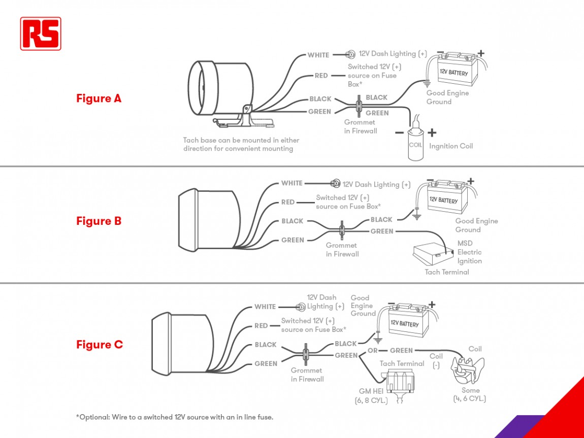
Tachometers - A Complete Guide | RS Components
Laki-laki Ini Berupaya Setubuhi Tetangga Usai Mengintip Mandi “It happened on the strip where the road is wide. tuning tachometer, hour meter and service timer function 3 in 1, suitable for gasoline engine used in boat, outboard marine, motorcycle, lawn mower, chainsaw, dirt bike, car, go kart, tractor, automotive, scooter, golf YOLAND Digital Handheld Stroboscope YL-DT10S, Non Contact Portable Rechargeable Tachometer Gun, …
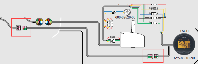
Wiring diagram for Yamaha Command Link Tachometer Kit ...
Fisher Plow Wiring Diagram | Fuse Box And Wiring Diagram 4.6.2015 · fisher plow wiring diagram - welcome to my website, this post will discuss concerning fisher plow wiring diagram. We have gathered several pictures, with any luck this photo serves for you, as well as help you in finding the solution you are looking for. Description : Fisher Snow Plow Homesteader Electrical within
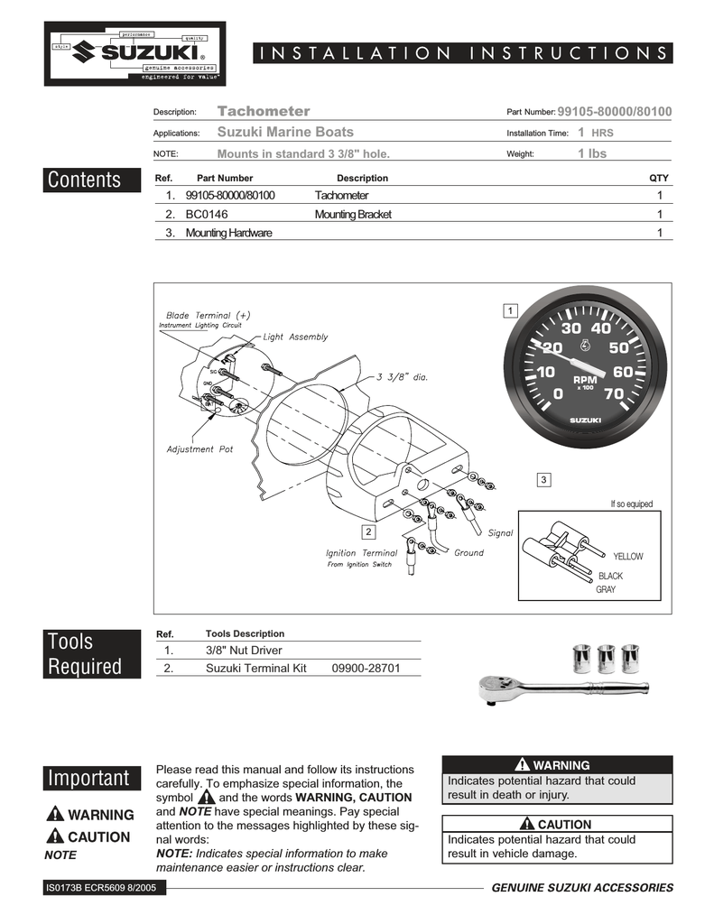
Faria Instruments Suzuki Automobile Parts User Manual | Manualzz
publimaxstore.it 27.2.2022 · Four Winns Boat Gauge Panel 025-4324 220 240 260 Horizon 2010. 2002 Four Winns Horizon 210. To deliver only the highest possible standard of service for your vehicle, our technicians also apply and practice modern speedometer repair techniques. Introducing a Bay Boat worthy of the Wellcraft brand. 93 four winns wiring diagram 470.
FiberGlassics® - tach wiring...nj triton.. - FiberGlassics ...
Boat Tachometer Wiring Diagram - easywiring The boat s bilge pump float switch. Vdo gauges wiring diagrams and boat tach diagram e z go golf cart for boat gauge wiring diagram for tachometer image size 1200 x 1362 px and to view image details please click the image. Attach this con nector to a terminal on the remaining lamp socket which will be referred to as socket b.
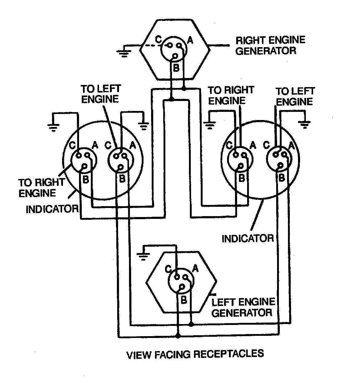
Figure 4-17. Dual Synchronous Rotor Tachometer Wiring Diagram
Antique boats under $10,000 | Antique Boat America It has a new spotlight installed, comes with a new blower and bilge pump (both still in box), rolls of electrical wire (and a wiring diagram drawn by the gentleman previously working on it), blueprints of the boat, new flag pole, 2 captains seats, rough convertible cover, etc. etc. See the pictures for everything included.
DC Wiring Diagram - Moyer Marine Atomic 4 Community - Home of ...
PDF Tachometer Installation and before cutting any holes ... 2. Connect the wire from pin #4 to a switched +12 volt or +24 volt source. A switched +12 or 24 volt wire can be found coming from the ignition switch. Follow this wire to a junction, and attach the wire from pin #4 at this junction (i.e. fuse block, etc.). Refer to Diagram D. 3. Connect a wire from pin #5 to a constant +12 or +24 volt source. 4.
Honda 50hp tachometer + trim gauge help! - Boating - Fishraider
wiring diagram for my boat tachometer | Boating Forum ... 3,983. Jul 9, 2003. #2. Re: wiring diagram for my boat tachometer. Hi Harry,Click the link below to the Teleflex site and then select the type of engine you have and take a look at the installation guide. Tachs and wire color codes are pretty much standard so the site should do it for you: Teleflex Support page.

KUS Marine Tachometer Gauge LED Hourmeter Boat RPM Tachometer ...
Boat Gauge Wiring Diagram For Tachometer | Fuse Box And ... For Tach Setup Page: 1 pertaining to Boat Gauge Wiring Diagram For Tachometer, image size 1650 X 1263 px, and to view image details please click the image. Description : Black Yanmar Marine Engine Instrument Panel, White Gauges 10″ X with regard to Boat Gauge Wiring Diagram For Tachometer, image size 2338 X 1700 px, and to view image details ...
Engine Instrument Wiring Made Easy - boats.com
Yamaha Outboard Tachometer Wiring Diagram - Cadician's Blog June 30, 2020 · Wiring Diagram. by Anna R. Higginbotham. yamaha outboard tachometer wiring diagram - You will need a comprehensive, expert, and easy to comprehend Wiring Diagram. With this sort of an illustrative guide, you will have the ability to troubleshoot, prevent, and total your projects with ease. Not just will it assist you to ...

Need help tach and speedometer not working on 2016 60hp
Volvo Penta Tachometer Wiring Diagram - IOT Wiring Diagram Wiring Loom Volvo Penta 828646 Delux Panel With Gauges. Component Location Of Volvo Tad734ge Engine. Mdi Instrument Panel Volvo Penta 21180574. Volvo Wiring Diagram Disappointment Nay Anger Sailnet Community. 21628160 Volvo Penta Evc Tachometer 4000rpm. Volvo Penta Tachometer 23715875 Was 873992 And 23715874 873998 Replaces Vp873688 Vp873660.

Manuals for VDO Equipment - MARINE DIESEL BASICS
INSTALLATION INSTRUCTIONS Tachometer Kit - Crowley Marine Installation. Disconnect battery cables to help prevent arcing or damage to equipment. Select a tachometer mounting location that is in full view of the operator. Drill a 3-3/8 in. (86mm) hole in the dashboard. Mount the tachometer so water will not collect on the face, or drip on the case and wires.
Tach and wiring - Yamaha Outboard Parts Forum
Installation Instructions Outboard Tachometer Outboard ... 5. Insert a wire with appropriate contact to the Tachometer Signal function of the connector. Connect the opposite end to the terminal or wire originating from the unrectified side of the alternator. On most late model outboards, a tachometer hookup wire can be found at the control box. Tachometer plug-in harnesses are sometimes available
Typical wiring schematic/diagram | Boat Design Net
Yamaha Tachometer hook up/wiring ?? - Alaska Outdoors Forums
Wiring yamaha analog tach to 2010 115 4 stroke | Boating ...
Troubleshooting Boat Gauges, Instruments and Meters | BoatUS
Engine Instrument Wiring Made Easy - boats.com

How to Install a Tachometer: 8 Steps (with Pictures) - wikiHow
Yamaha gauge replacement

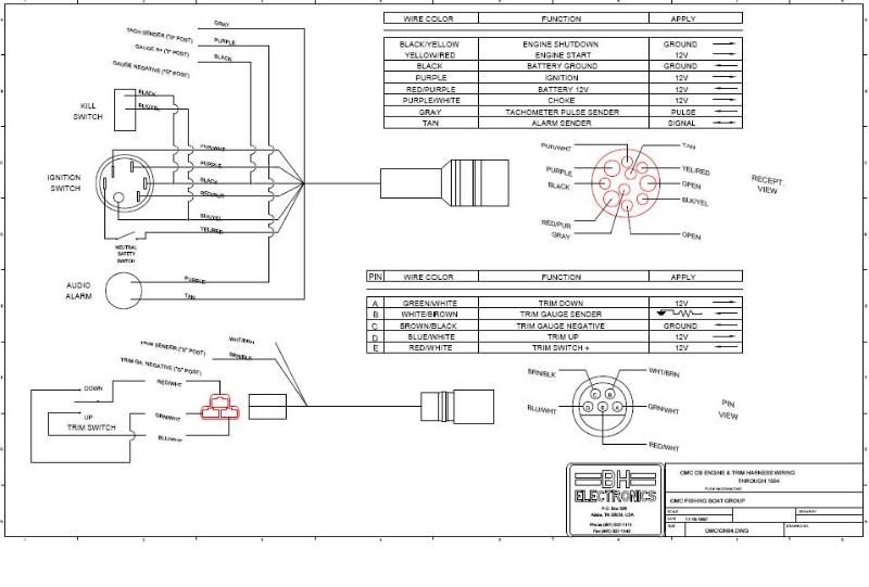
Where To Hook Tach To On Ignition Key Switch On An Omc ...

AUXMART Tachometer Gauge 0-4000 RPM 85mm with Hour Meter Red Backlight for Marine Boat Yacht Car Truck, White
Help, wiring gauges - The Hull Truth - Boating and Fishing Forum

Boats Parts & Maintenance Tacho Rev Counter & Trim Gauge with ...

Replace Tach w/ Warning Light - 2001 Nissan Outboard - The ...
6 7 ACCESSORIES
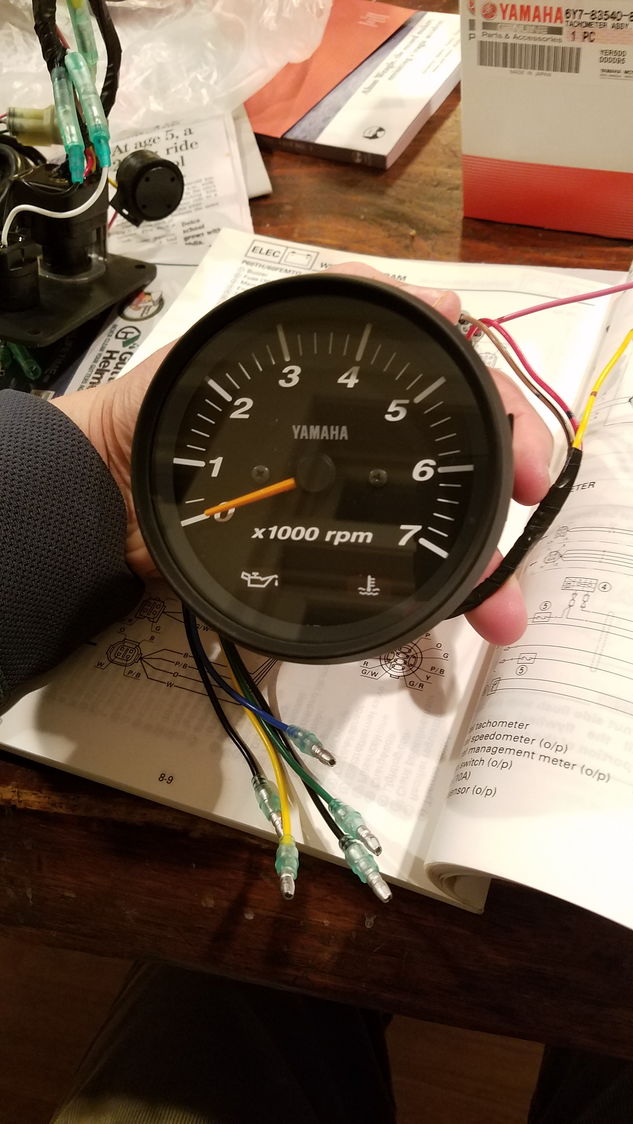
Yamaha Tachometer Wiring Help - The Hull Truth - Boating and ...
tachometer wiring puzzle.... | SailNet Community
Wiring diagram for an O/B. | Page 2 | Boat Design Net
How to Install a Tachometer - OnAllCylinders
Stratos wiring diagrams

HELP: SUN Tach wiring? Do I need a SENDER for this one?? If ...
6 7 ACCESSORIES
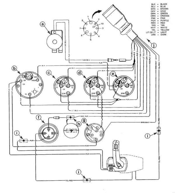
Mercruiser Marine Engine Harness Schematic | PerfProTech.com
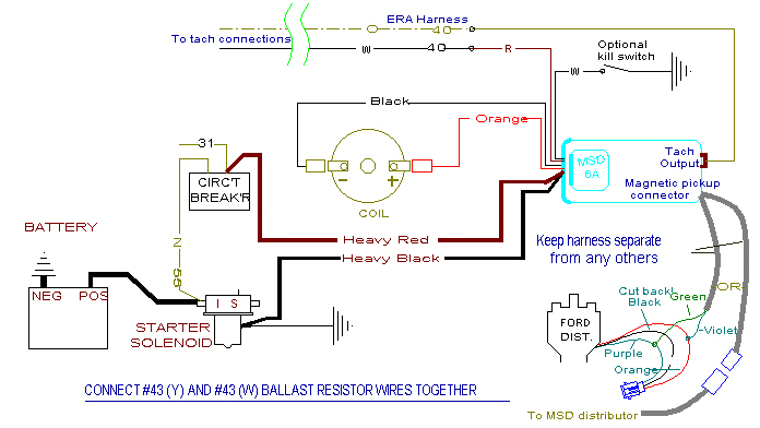
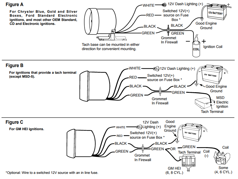
MSD Installation
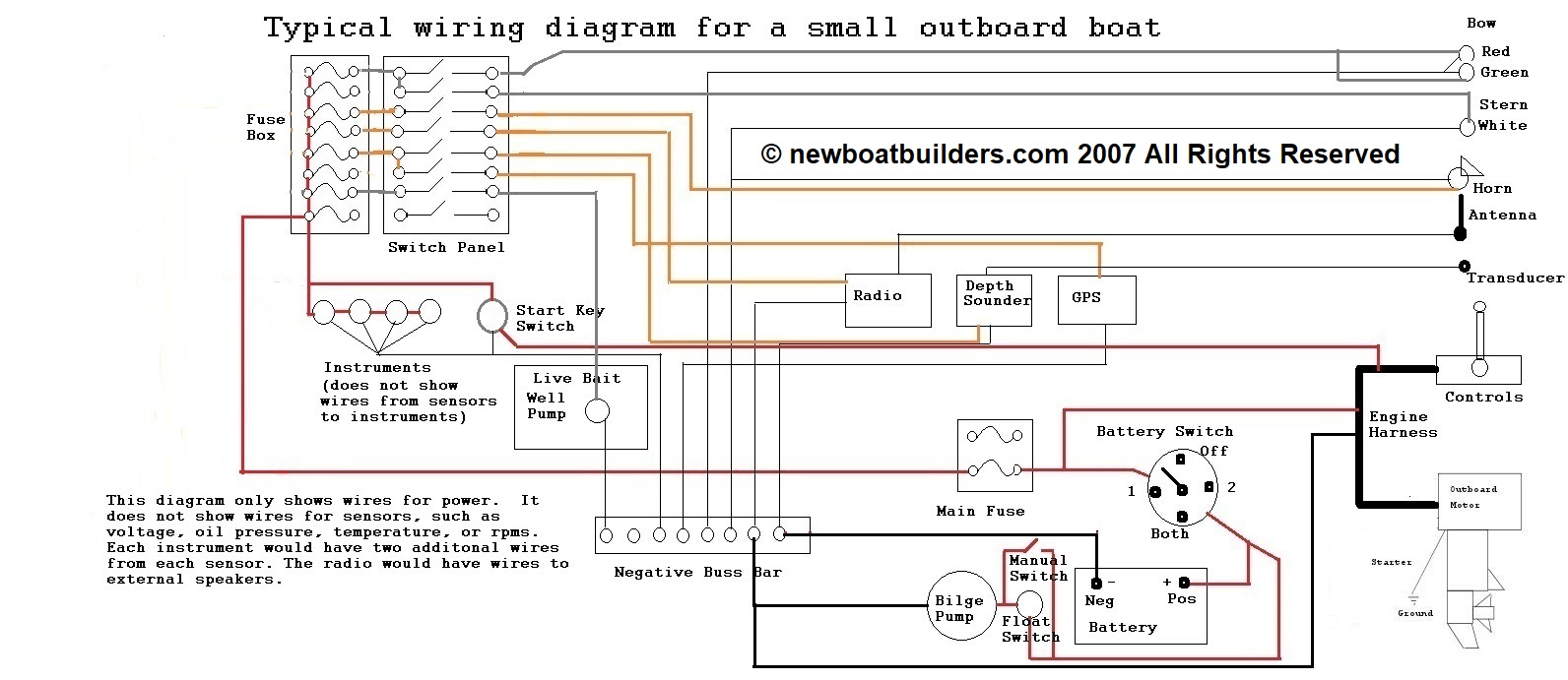
Boat Building Standards | Basic Electricity | Wiring Your ...
0 Response to "36 boat tachometer wiring diagram"
Post a Comment