38 potter brumfield relay wiring diagram
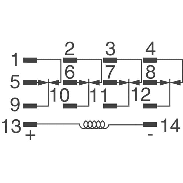
Potter Brumfield Relay Wiring Diagram Download - Wiring ... Assortment of potter brumfield relay wiring diagram. A wiring diagram is a streamlined standard pictorial representation of an electrical circuit. It shows the components of the circuit as simplified forms, and also the power and also signal connections in between the tools. KRPA-11AG-120-TE-Connectivity-datasheet-7085179.pdf General Purpose Relay. File E29244, E22575, E81558 (KR Hermetic) ... Use 110V relay with 10,000 Ω 5W Resistor in series ... Wiring Diagrams (Bottom Views).
Potter & Brumfield General Purpose Panel/Plug-in Relays ... subject to change. Potter & Brumfield. General Purpose. Panel/Plug-in Relays. KRPA Series Panel Plug-in Relay. Potter & Brumfield. Coil Data (continued).3 pages

Potter brumfield relay wiring diagram
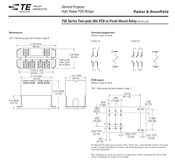
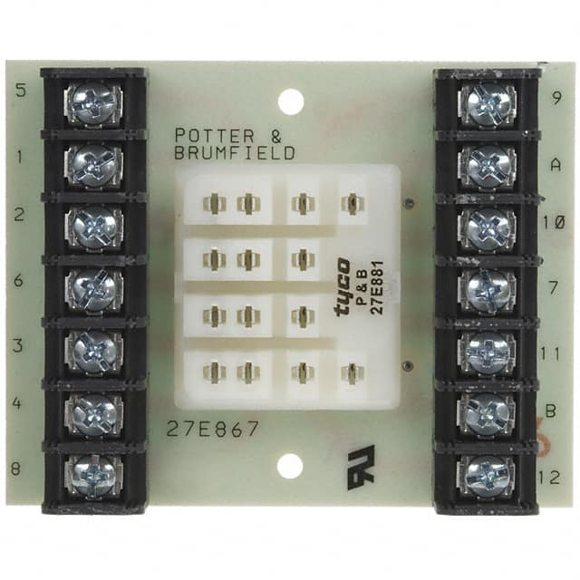
Potter Brumfield Relay Diagram - MaxNews Potter Brumfield Relay Wiring Diagram - General Wiring Diagram Potter & Brumfield 27E121 11-Pin Relay Socket USED | eBay S89R11DAC1-12 TE Connectivity Potter & Brumfield Relays ... PDF General Purpose Relays Industrial Relays Potter & Brumfield DC coil Enclosed relays, 4 pole: -45ºC to 50ºC Enclosed relays, 1-3 pole: -45ºC to 70ºC Open relays: 15ºC higher maximum AC coil Enclosed relays, 3 and 4 pole: -45°C to +45°C Enclosed relays, 1 and 2 pole: -45ºC to +55ºC Open relays: 15°C higher maximum Maximum allowable ambient temperature vs voltage (KUP enlcosed) Dimensions Potter & Brumfield Tyco - Micro-Semiconductor.com Printed Circuit Board Relay. F E AT U R E S. • 1-5Arating. • Low Profile package ... Wiring Diagram. (Bottom Vi e w ). Code 2. T73L1D15-05.23 pages
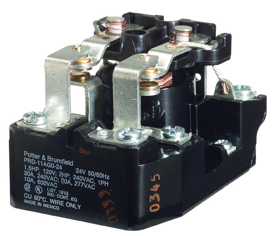
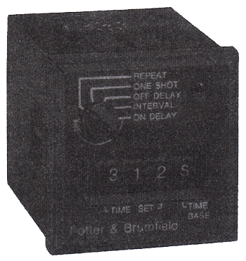
Potter brumfield relay wiring diagram. PDF POTTER & BRUMFIELD Power Relays and Contactors Wiring Diagram INPUT 63.50 max. 69.85 max.• 69.85 max. 90.81 max. 76.20 max. 63.50 max. 96.52 max. 64.77 max. 100.97 max. Coil Voltage Coil Voltage Coil Voltage POTTER & BRUMFIELD Power Relays and Contactors A B For quantities of 200 and up, call for quote. PRD SERIES: HEAVY DUTY POWER RELAYS For quantities of 200 and up, call for quote ... Potter & Brumfield Relays and Circuit Breakers | TE ... Potter & Brumfield Relays for appliances, HVAC, and industrial controls. Our Potter & Brumfield portfolio includes different types of relays and contactors as well as circuit breakers. Our components consist of thermal and magnetic types, protecting equipment across multiple application settings. Wiring Diagram for Potter&Brumfield PM-17AY-120 ... ohm resistor in series with the relay coil, it should limit. the current through the coil to ~120 mA. The resistor will. get hot - it will dissipate about 15 watts of heat. To give. yourself a bit of help in getting rid of the heat, I'd use. 4 250 ohm 10 watt resistors in series. 1/4 of the heat will. PDF POTTER & BRUMFIELD Time Delay Relays General Purpose Relays Potter & Brumfield 1780 45.20 61.10 74.60 35.71 38.89 48.41 35.71 38.89 54.76 35.71 38.89 73.66 Plain Case Syle Shown 42.24 61.11CL SERIES: COMPACT TIME DELAY RELAYS 76.60 47.80 47.80 71.90 47.80 3 6 9 1 4 7 A B 3 6 9 1 4 7 2 5 A B 1 11 Input External Control Switch 1 8 Input * Note: Input polarity for DC operation.
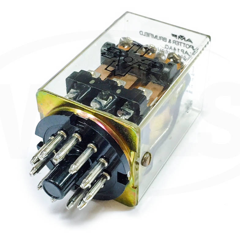
Potter Brumfield Relay Wiring Diagram Krp - schematron.org Potter Brumfield Relay Wiring Diagram Krp. Potter Brumfield 8 Pin Relay Wiring Diagram Auto Electrical Wiring. p b rh industrialelectronics biz 3 Pole Relay Schematic KRP Relay Wiring. Designed or power circuits such . The KRP is the KR relay enclosed in a clear KRP When ordering, specify coil voltage and frequency. A.C. Potter Brumfield Relay Wiring Diagrams Cwb 38 76000 Potter Brumfield Relay Wiring Diagram Cwb 38 76000. Each circuit displays a distinctive voltage condition. You are able to easily step up the voltage to the necessary level utilizing an inexpensive buck-boost transformer and steer clear of such issues. The voltage is the sum of electrical power produced by the battery. 11 Pin Relay Wiring Schematic - The Wiring Potter brumfield 8 pin relay wiring diagram auto electrical wiring. A wiring diagram usually gives instruction roughly the relative approach and union of devices and terminals on the devices, to incite in building or servicing. Ford Aod Transmission Wiring Harness Reading Industrial | pdf . 3 Conductor Teck Cable. PDF General Purpose Panel/Plug-in Relays Potter rumfield ... KRPA Series Panel Plug-in Relay Potter & Brumfield Coil Data (continued) Coil versions, AC coil Coil Rated Operate Coil Rated coil code voltage voltage resistance power 6 6 5.1 6 2.01 12 12 10.2 24 2.02 24 24 20.4 85 2.02 120 120 102.0 2250 2.1 240 240 204.0 9110 2.1 ...
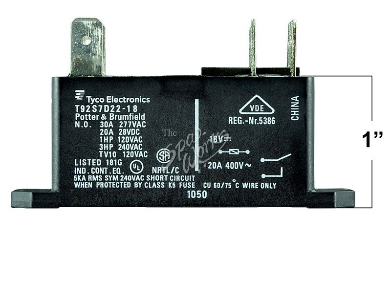
T92S7D22-22 - Carrier OEM Replacement Furnace Relay by ... TE CONNECTIVITY / POTTER & BRUMFIELD T92P7D22-12 POWER RELAY, 12VDC, 30A, DPST-NO, FLANGE. ... I've double checked the wiring diagram on the unit to make sure it's hooked up correctly. Seems just like it fails after a couple years on it's own without even being engaged. 1-star, but no other choice since it the part my OEM used for their unit. KRPA-14AN-120 : Potter & Brumfield Power Relays | TE ... KRPA-14AN-120. Active. Potter & Brumfield KRPA, Power Relays, Industrial Panel Plug-In, Monostable, AC, 2.1 VA Coil Power Rating AC, 2250 Ω Coil Resistance. Potter & Brumfield. Potter & Brumfield Sda-2056 Wiring Diagram Assortment of potter brumfield relay wiring diagram. A wiring diagram is a streamlined standard pictorial representation of an electrical circuit. It shows the components of the circuit as simplified forms, and also the power and also signal connections in between the tools. Vf4 45f11 Wiring Diagram - schematron.org VFF11; VFF A simple wiring diagram would be most appreciated. . automotive supply and get yourself a Tyco or poter brumfield #vff11 40 amp relay. VF4 A (Standard, Shrouded and Weatherproof). Plug-In Relays. Mini ISO . Circuit Diagram. C0. 1 Changeover contact/1 Form VFFS 1- VF_ _ (Without Bracket) & VF_ _(With Bracket).
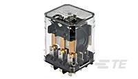
KUP-11A15-120 : Potter & Brumfield Power Relays | TE ... Active. Potter & Brumfield KUP, Power Relays, Industrial Panel Plug-In, Monostable, AC, 2.1 VA Coil Power Rating AC, 2250 Ω Coil Resistance. Potter & Brumfield. Potter & Brumfield KUP. TE Internal #: 1-1393117-9. TE Internal Description: KUP-11A15-120=KU.
Potter Brumfield Relay Wiring Diagram - Free Wiring Diagram Potter Brumfield Relay Wiring Diagram February 19, 2019 by Larry A. Wellborn Assortment of potter brumfield relay wiring diagram. A wiring diagram is a streamlined traditional photographic depiction of an electrical circuit. It shows the elements of the circuit as streamlined forms, as well as the power and signal links in between the gadgets.
Potter Brumfield Relay Wiring Diagram Collection Potter Brumfield Relay Wiring Diagram. To properly read a wiring diagram, one provides to find out how the particular components in the program operate. For instance , in case a module is powered up also it sends out the signal of half the voltage plus the technician will not know this, he would think he provides a problem, as he or she would ...
List of Potter & Brumfield Relays Models & Products | TE ... Search our portfolio of Potter & Brumfield Relays products and select your specifications. We offer a wide array of reliable and cost-effective products from standard solutions to custom designs. TE Connectivity (TE) Need Help? +1 800 522 6752 or Live Chat
Potter Brumfield Relay Wiring Diagram Collection - Wiring ... Please download these potter brumfield relay wiring diagram by using the download button, or right select selected image, then use Save Image menu. Wiring diagrams help technicians to find out what sort of controls are wired to the system. Many people can read and understand schematics generally known as label or line diagrams.
Potter & Brumfield Tyco - Micro-Semiconductor.com Printed Circuit Board Relay. F E AT U R E S. • 1-5Arating. • Low Profile package ... Wiring Diagram. (Bottom Vi e w ). Code 2. T73L1D15-05.23 pages
PDF General Purpose Relays Industrial Relays Potter & Brumfield DC coil Enclosed relays, 4 pole: -45ºC to 50ºC Enclosed relays, 1-3 pole: -45ºC to 70ºC Open relays: 15ºC higher maximum AC coil Enclosed relays, 3 and 4 pole: -45°C to +45°C Enclosed relays, 1 and 2 pole: -45ºC to +55ºC Open relays: 15°C higher maximum Maximum allowable ambient temperature vs voltage (KUP enlcosed) Dimensions
Potter Brumfield Relay Diagram - MaxNews Potter Brumfield Relay Wiring Diagram - General Wiring Diagram Potter & Brumfield 27E121 11-Pin Relay Socket USED | eBay S89R11DAC1-12 TE Connectivity Potter & Brumfield Relays ...













0 Response to "38 potter brumfield relay wiring diagram"
Post a Comment