37 physical vs logical network diagram
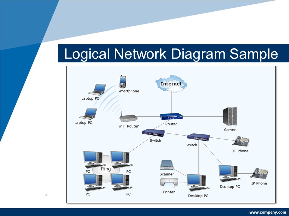
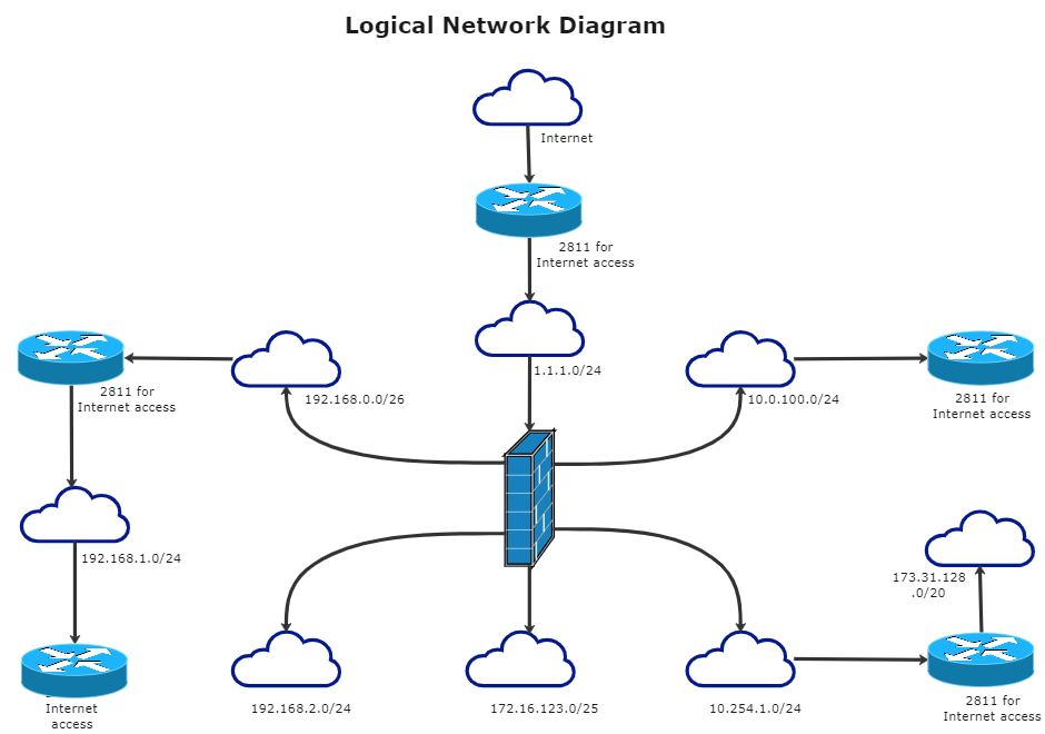
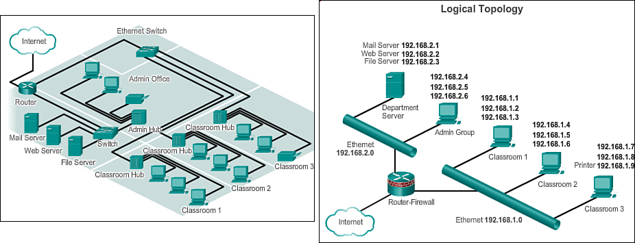
Logical Network Diagram: A Complete Tutorial | EdrawMax The logical network diagram shows how the data behaves and flows between the devices in a network. The physical network diagram is what its name shows. This type of network diagram shows you the physical devices and the cables connected. The lines in a logical network diagram illustrate the flowing of data between devices in a computer network. Difference Between Physical and Logical Topology (with ... Unlike physical topology, the logical topology emphasis on the manner in which data is transmitted between network nodes instead of the physical layout of the path that data follows. An important fact regarding these topologies is that both physical and logical topologies are independent regarding a network, whether it is of any shape and size.
Logical Architecture vs Physical Architecture - Simplicable Logical architecture is a structural design that gives as much detail as possible without constraining the architecture to a particular technology or environment. For example, a diagram that illustrates the relationship between software components. Physical architecture gives enough detail to implement the architecture on a technology.

Physical vs logical network diagram
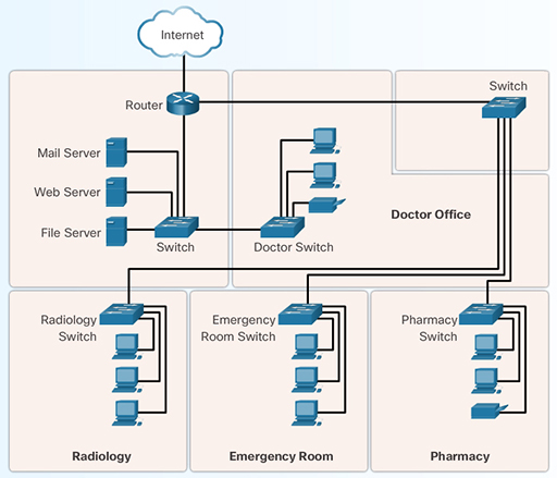
Difference between Physical and Logical Topology ... Physical Topology Logical Topology. Depicts physical layout of network. Depicts logistics of network concerned with transmission of data. The layout can be modified based on needs. There is no interference and manipulation involved here. It can be arranged in star, ring, mesh and bus topologies. It exists in bus and ring topologies. Logical vs. Physical Data Flow Diagram | EdrawMax Online Logical vs. Physical Data Flow Diagram The differences and similarity will be illustrated in the following part. Developing Logical Data Flow Diagram Logical data flow diagrams demonstrate how the organization works. The processes depict the business's operations. The data stores reflect the collected data irrespective of how the data is processed. What is a Network Diagram | Lucidchart A network diagram can be either physical or logical. Logical network diagrams A logical network diagram describes the way information flows through a network. Therefore, logical network diagrams typically show subnets (including VLAN IDs, masks, and addresses), network devices like routers and firewalls, and routing protocols.
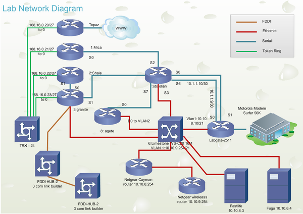
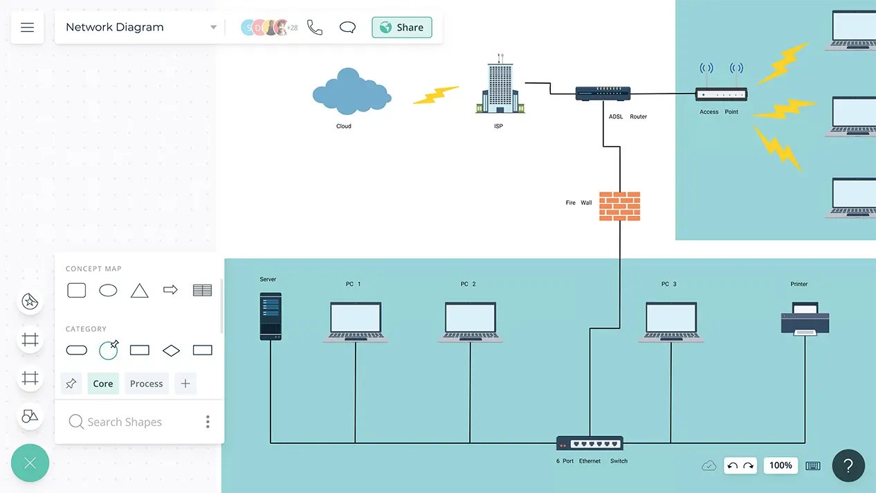
Physical vs logical network diagram. Logical vs Physical Data Flow Diagrams - Visual Paradigm Data flow diagrams (DFDs) are categorized as either logical or physical. A logical DFD focuses on the business and how the business operates. It describes the business events that take place and the data required and produced by each event. On the other hand, a physical DFD shows how the system will be implemented. Here are the main differences between logical and physical DFD: What is the difference between a logical network diagram ... A logical network diagram usually shows network devices like routers, firewalls, and voice gateways. A physical network diagram shows how the network devices are physically connected together, and therefor all ports on all devices on the network are represented here. This will include cables. What Is a Network Diagram? - Auvik Networks Inc. Network diagrams come in different shapes and sizes, but can generally be classified as either a physical network diagram or a logical network diagram. It's important to recognize the difference between these two diagram types, as they communicate different information. Network Diagram Software Logical Network Diagram | Logical ... Network Diagram Software Logical Network Diagram "Logical topology, or signal topology, is the arrangement of devices on a computer network and how they communicate with one another. How devices are connected to the network through the actual cables that transmit data, or the physical structure of the network, is called the physical topology.
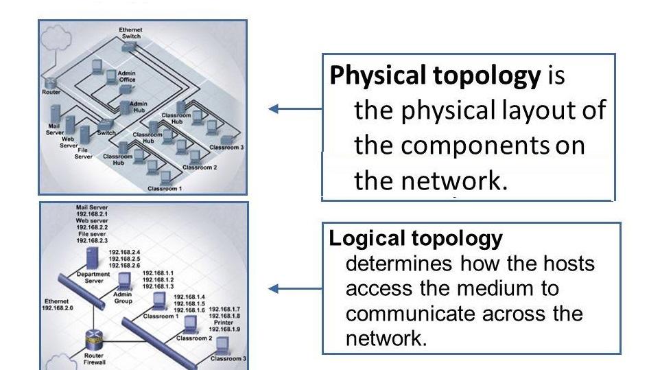
Network Topologies: Logical vs Physical | Aruba Blogs Sep 24, 2019 · Physical network topology is the placement of the various components of a network and the different connectors usually represent the physical network cables, and the nodes represents usually the physical network devices (like switches). Logical network topology illustrates, at a higher level, how data flows within a network. Logical vs. Physical Data Flow Diagram | Lucidchart A logical DFD focuses on the business and business activities, while a physical DFD looks at how a system is implemented. So while any data flow diagram maps out the flow of information for a process or system, the logical diagram provides the "what" and the physical provides the "how.". They are two different perspectives on the same ... The Logical Network Diagram Explained | EdrawMax Online Network diagrams include two different types: logical network diagram and physical network diagram. A logical network diagram explains the logical components of the devices of a network, it includes cables and hardware. Just like the floor plan, it shows the physical layout of a network. Logical network topology diagram | Network Diagram ... Logical network topology diagram. "Logical topology, or signal topology, is the arrangement of devices on a computer network and how they communicate with one another. How devices are connected to the network through the actual cables that transmit data, or the physical structure of the network, is called the physical topology.
Logical vs. Physical Network Diagrams | DCIM, Network ... Logical Network Diagrams. A logical network diagram describes how information flows through a network. Logical diagrams typically show subnets (including VLAN IDs, masks, and addresses), routers, firewalls, and its routing protocols. Note that we will be discussing the Open Systems Interconnection (OSI) model when discussing logical network diagrams — click here for an in-depth reference of the OSI model.. With netTerrain, you can create any logical diagrams, including: Layer 1, 2, and 3. Physical Network Diagrams Explained | DCIM, Network ... Within the OSI model of networking, logical diagrams are referred to as 'L2'. A physical network diagram will, ideally, show the network topology exactly as it is: with all of the devices and the connections between them. Difference between physical topology and logical topology A physical network topology diagram shows the structure of how devices are connected physically inside a network. A logical network topology diagram shows the logical method of communication used by the devices inside the network for network communication. Physical topology specifies the layout how devices are physically connected in the network. System Modeling: Understanding Logical and Physical ... The goal of both logical and physical architecture specifications is to define and document the logical and physical components of a system, respectively, in order to provide clarity around how those component elements relate to one another. The artifacts resulting from either effort could be text documentation, or diagrams, and both have their own advantages… Read More »System Modeling ...
Physical Network Design Process Define the Logical ...
Logical Network Diagram Vs Physical Network Diagram - Diagram ... Aug 03, 2021 · Logical Network Diagram Vs Physical Network Diagram. angelo on August 3, 2021. Join Leading Researchers in the Field and Publish With Us. Ad Journal of Electrical and Computer Engineering is a Peer-Reviewed Open Access Journal. Lan Topology Diagram Internet Setup Wifi Internet Wifi Router.
Network Layout Tool - Edraw
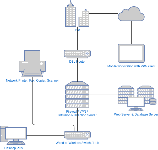
What Is a Network Diagram? (Plus How To Create One ... You can divide network diagrams into two types: logical and physical. The following are the differences between a physical and logical network diagram: A physical network diagram displays the physical layout of equipment, whereas a logical network displays the network topologies and how information flows in the company.

Logical network topology diagram | Physical Topology Diagrams ...
Physical and logical networks - IBM A logical network is a portion of a physical network that connects two or more logical network interfaces or devices. A logical network interface or device is the software entity that is known by an operating system. There is a one-to-one mapping between a physical network interface/device and a logical network interface/device.
Internet of everything - OpenLearn - Open University
Logical vs. Physical Network Diagrams - DNSstuff Diagramming networks accurately relies on understanding the underlying topologies. Topologies describe the layout of elements in a network and the connections between them. There are a few main types of network topologies, which can apply to both physical and logical network layouts. While the topic is thoroughly covered in other articles, it’s worth reiterating the basic topology types. A star topology arranges nodes around a central hub. In a bus topology, devices are arranged along a line, with data flowing in one direction. In a ring topology, each node is connected only to the ones on either side, so data flows in a circle. Other possible topologies include dual-ring, which allows data to flow two directions in a circle, a tree topology with a branching structure, and a mesh topology where individual nodes are connected to multiple other nodes. Each of these topologies has its advantages and disadvantages in terms of data flow, efficiency, cost, and other factors. As is further...
Physical and Logical Network topology - Huawei Enterprise ...
visualization - Difference between physical and logical ... In network topologies, a logical topology often describes the paths that data can take across a network irrespective of how the wires are plugged into each other. A "physical" view of a system describes the "stuff" that makes up the system, or describes how the system is connected together in the physical world.
Logical Network Diagram - ppt video online download
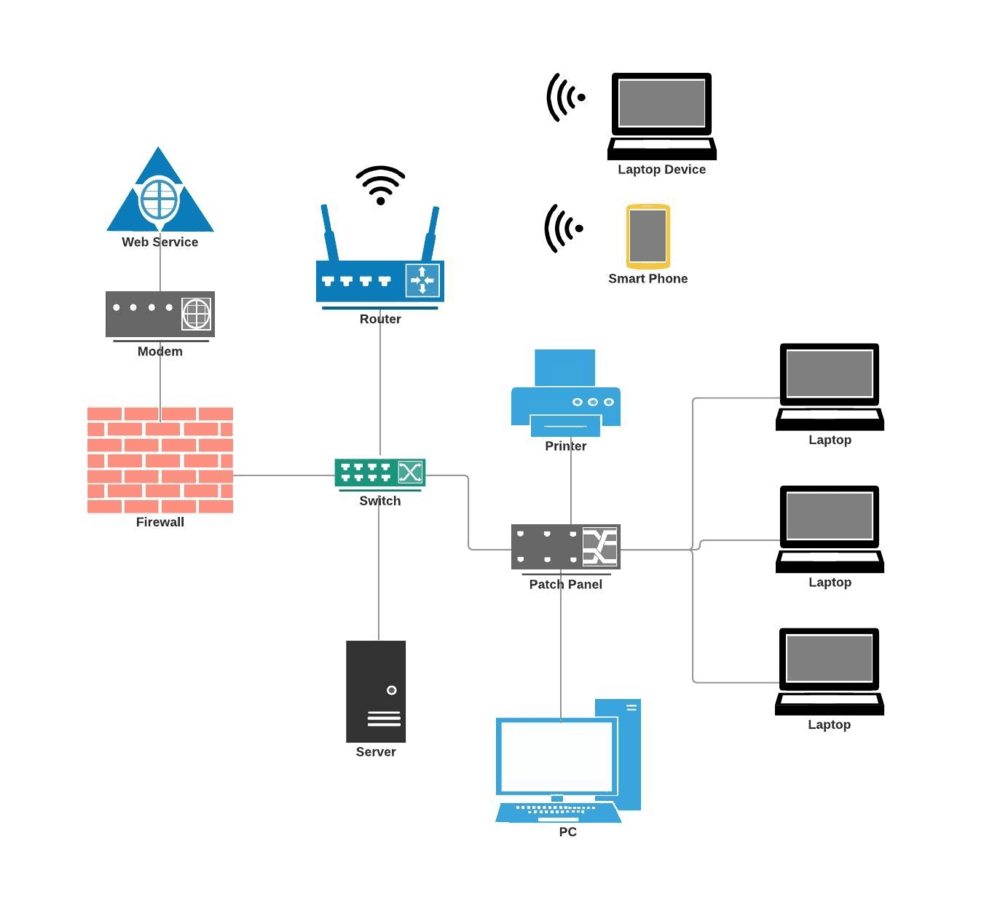
What is a Logical Network Diagram? (with pictures) A physical network diagram shows the physical connections of network components, while a logical one shows how they relate and communicate with each other. Printers, modems, switches, routers, mobile devices, and more can all be part of a logical network diagram.
Logical Network Diagram: A Complete Tutorial | EdrawMax
Physical Vs Logical Architecture Diagram - an introduction ... Physical Vs Logical Architecture Diagram. Here are a number of highest rated Physical Vs Logical Architecture Diagram pictures on internet. We identified it from well-behaved source. Its submitted by paperwork in the best field.
The Logical Network Diagram Explained | EdrawMax Online
Logical and Physical Network Topology Diagram | SolarWinds A physical network diagram depicts the network topology with the physical aspects like ports, cables, racks, and more. A logical network diagram, on the other hand, shows the "invisible" elements and connections flowing through the physical objects on the network. Therefore, physical vs. logical network diagrams offer two different perspectives on and representations of the same network.

What is a Network Diagram | Lucidchart
Physical & Logical Topology: Definition & Characteristics ... A logical topology describes how network devices appear to be connected to each other. For example, in a logical diagram of your office network, you may show a connection between city A and city B....
Network Diagram Software Physical Network Diagram | Logical ...
Main Difference Between Physical and Logical Topology ... The potentials of the network access devices and media decides the physical topology of a network. In terms of arithmetic, the physical topology of a network is the real arithmetical arrangement of workstations. Logical topology shows the temperament of the courses the way signals move from node to node. The network administrator configures these topologies at the physical layer of 7 layer OSI model in networking.
Logical Security Architecture - DANIEL PRATT
What is a Network Diagram | Lucidchart A network diagram can be either physical or logical. Logical network diagrams A logical network diagram describes the way information flows through a network. Therefore, logical network diagrams typically show subnets (including VLAN IDs, masks, and addresses), network devices like routers and firewalls, and routing protocols.
Logical Network Diagram: A Complete Tutorial | EdrawMax
Logical vs. Physical Data Flow Diagram | EdrawMax Online Logical vs. Physical Data Flow Diagram The differences and similarity will be illustrated in the following part. Developing Logical Data Flow Diagram Logical data flow diagrams demonstrate how the organization works. The processes depict the business's operations. The data stores reflect the collected data irrespective of how the data is processed.

Initial Network - an overview | ScienceDirect Topics
Difference between Physical and Logical Topology ... Physical Topology Logical Topology. Depicts physical layout of network. Depicts logistics of network concerned with transmission of data. The layout can be modified based on needs. There is no interference and manipulation involved here. It can be arranged in star, ring, mesh and bus topologies. It exists in bus and ring topologies.

Tracing Logical Network Packets Through Physical Network ...

Network diagram tool that supports interface labels? : r/linux
Network Diagram Software | Draw Network Diagram Online | Creately

Try these 5 diagramming tools for network architecture ...

Logical and Physical Network Topology Diagram | SolarWinds

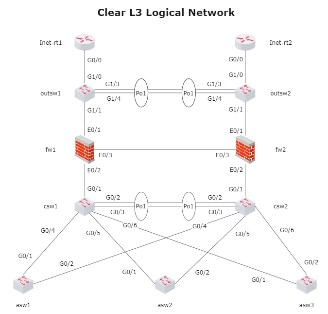
How to Draw Clear L3 Logical Network Diagrams - Packet Pushers
Network Diagram Software

ParticipanDiagrams – Campus Network Design & Network Management

Logical vs. Physical Network Diagrams | DCIM, Network ...

Physical Network Diagrams Explained | DCIM, Network ...

Logical vs. Physical Network Diagrams | DCIM, Network ...

Dell VRF-lite & VMware NSX: Multitenancy Across Physical ...
7 Best Network Diagram Software + Free Guide - DNSstuff

What is a Logical Network Diagram? (with pictures)

The logical and physical networks | Download Scientific Diagram

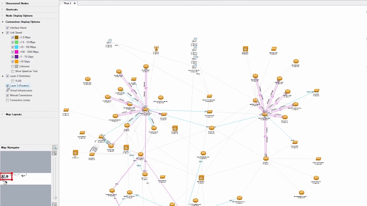
Global network topology diagram showing how the data ...

Mapping of physical sensor devices to the logical network ...
LANs, WANs, and the Internet (1.3) > Exploring the Modern ...
Logical vs. Physical Network Diagrams - DNSstuff
How To Design A Network Topology | Jones IT

Network Diagram Software Logical Network | Network Diagram ...

What is a Network Diagram | Lucidchart

Differences between Physical and Logical topology
Network Diagram Software | Quickly Create High-quality ...
0 Response to "37 physical vs logical network diagram"
Post a Comment