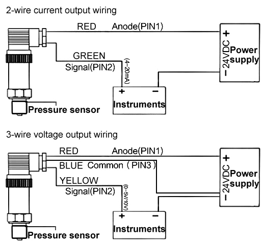
37 4 Wire Pressure Transducer Wiring Diagram
4 20ma Pressure Transducer Wiring Diagram Gallery - Wiring ... Jul 07, 2018 · Wiring Diagram Images Detail: Name: 4 20ma pressure transducer wiring diagram – 4 20ma Transmitter Circuit Diagram Best 3 Wire Pressure Transducer Wiring Diagram. File Type: JPG. Source: golfinamigos.com. Size: 101.01 KB. Dimension: 985 x 729. Wiring 554-102 fuel pressure transducer? - Holley I spliced into Auto Meter's signal wire, ran a new 22 gauge wire to the ECU, removing the existing purple wire in A31. I don't know why it's not working. The EFI software, ECU pin J1A-A31 is just reading for a 0-5V signal. The Holley EFI 554-102 sensor has a linear voltage output range of .5 - 4.5 volts (0- 100 psi).
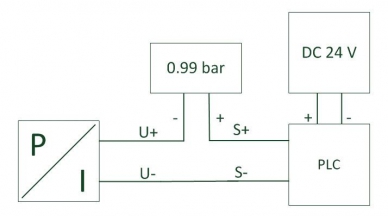
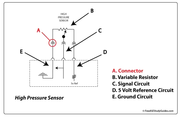
Trying To Find a 4 Wire Pressure Transducer | Automation ... If the Tx has 4 wires and a 5 VDC supply then the output could be 1-5 VDC, 0-5 VDC, 0-20 mA or 4-20 mA. Testing the digital indicator with a power supply or calibrator could determine the electrical range. Yes a 3 wire Tx will work, you need to determine a common connection between the 5VDC supply and the digital meter.
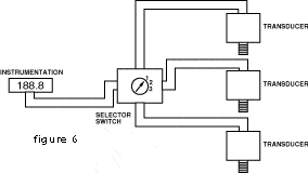
4 wire pressure transducer wiring diagram
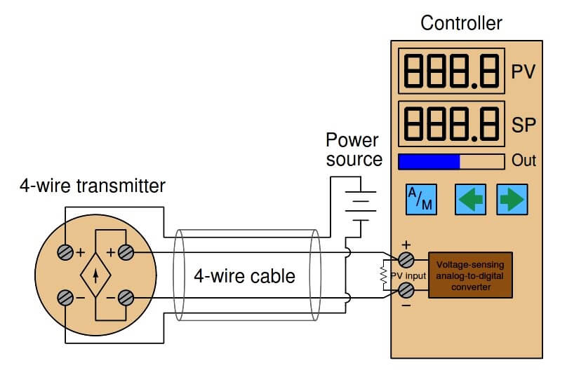
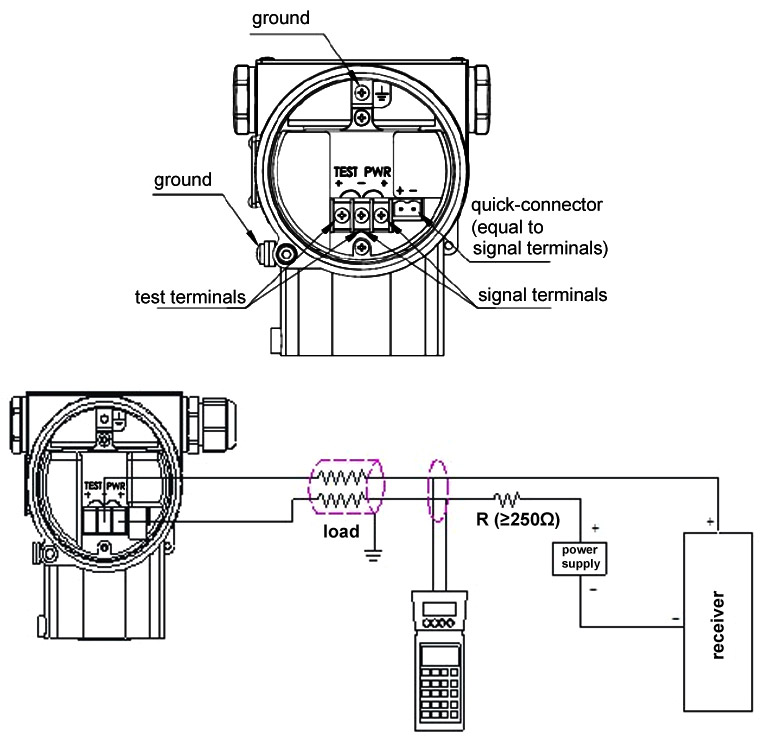
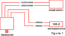
4-wire Transmitters Current Loops - InstrumentationTools These transmitters are called "4-wire" or "self-powered" units. The current signal from the transmitter connects to the process variable input terminals of the controller to complete the loop: Note : Here in this article, we are assuming a simple microcontrollers based controllers is connected with a 4 wire transmitters. Diagram 2, 3, 4 - wire transmitter working principle and ... 4 wire transmitter wiring diagram The figure above shows the wiring diagram of the four-wire transmitter. Most of the power supply is AC 220V, and some are DC 24V. DC4 ~ 20 ma output signals and the load resistance is 250 Ω, or DC0-10 ma, load resistance to 0-1.5 K Ω; Some also have mA and mV signals, but the load resistance or input resistance, Pressure Sensor & Wiring Diagram - YouTube Pressure Sensor & Wiring DiagramAmazon Printed Bookshttps:// Kindle Editionhttp:// ...
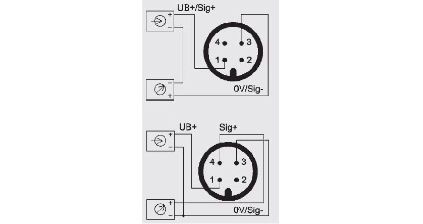
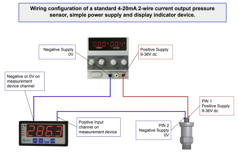
4 wire pressure transducer wiring diagram. Difference of 4-20 mA in 2-wire & 3-wire ... - WIKA blog What exactly is the difference between the 4-20 mA output signal in 2- and 3-wire technology? This question is answered best from the viewpoint of the user: An output signal in 2-wire technology means: less wiring required. better EMC protection, since interferences can be filtered more easily. better protection against wiring errors. 4 Wire Pressure Transducer Wiring Diagram - autocardesign May 29, 2020 · 4 Wire Pressure Transducer Wiring Diagram – wiring diagram is a simplified adequate pictorial representation of an electrical circuit. It shows the components of the circuit as simplified shapes, and the skill and signal connections along with the devices. A wiring diagram usually gives guidance nearly the relative slant and bargain of ... 4-20ma Pressure Transmitter Wiring - Micro Sensor Figure 1. It is a typical usage of two-wire 4-20mA pressure transmitters for most customers showed in figure 1. After the pressure transmitter is powered on, the loop current is proportional to the pressure to generate a 4-20 mA signal by collecting the pressure. The current flow through the sampling resistor (typical 100 Ω, 250 Ω) which ... 4 Wire Wiring Diagram - U Wiring 4 wire wiring diagram. Connect the end of the. The black sometimes red 12v and blue electric brakes wire may need to be reversed to suit the trailer. I show all of this in the above video. The wire pair colors are blue orange green and brown. Interactive electrical wiring diagram for DIY camper van conversion skoolie RV.
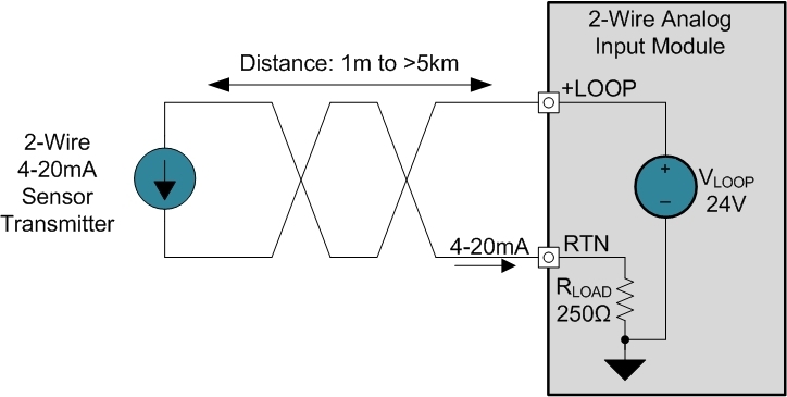
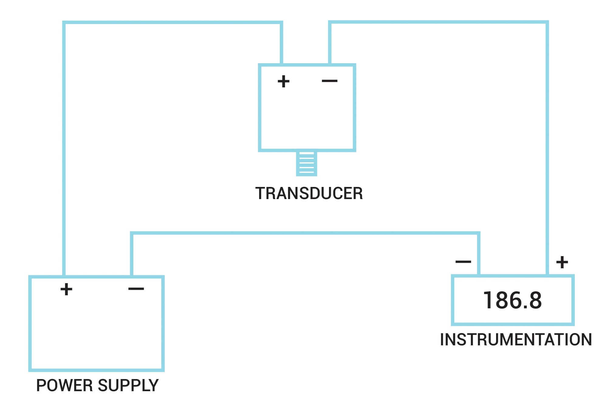
2 Wire Pressure Transducer Wiring Diagram Gallery - Wiring ... Source: omega.co.uk. Size: 12.43 KB. Dimension: 220 x 147. DOWNLOAD. Wiring Diagram Pics Detail: Name: 2 wire pressure transducer wiring diagram - 4 20ma Transmitter Circuit Diagram Awesome 3 Wire Pressure Transducer Wiring Diagram. File Type: JPG. Pressure Transducers |Installation and Wiring Diagrams Apr 17, 2019 · Pressure transducers that output milliamp signals can connect to multiple devices in series. The fact that they can transmit signals over long distances without interference makes it easier to connect a milliamp-signal device to multiple instrumentation units. This diagram illustrates the correct wiring. 4 Wiring Rotary Diagram Position Switch [MPBD6W] Search: 4 Position Rotary Switch Wiring Diagram. HQRP 4-Position 3-Speed Rotary Switch with Knob; 4 Postion Rotary Easy quick connect wire termination for quick and painless installs (just 5 out of 5 stars 5 $6 HQRP 4-Position 3-Speed Rotary Switch with Knob; 4 Postion Rotary Easy quick connect wire termination for quick and painless installs (just ) When troubleshooting any problem, first ... What are 2-wire and 4-wire Transmitter Output ... - RealPars - The actual wiring between the transmitter and the power supply depends upon whether it is a 2-wire or a 4-wire type. - A 4-wire transmitter has 2 wires connected to a power supply, and 2 signal wires connected to the PLC. - A 2-wire transmitter has only 2 wires and is connected in series with the power supply and the PLC.
PDF Quick Start Guide Rosemount 3051 Pressure Transmitter ... vent path is 360° around the transmitter between the housing and sensor. (See Figure 2-4.) Keep the vent path free of any obstruction including but not limited to paint, dust, and lubrication by mounting the transmitter so that fluids can drain away. Figure 2-4: In-line Gage Low Side Pressure Port. A. A. Pressure port location. March 2021 ... PDF Technical Reference - Turck "AN6(7)" and "AP6" 3-Wire DC Outputs Figure 12 Electronic Output Circuit Figure 13 Wiring Diagram Figure 10 Electronic Output Circuit Figure 11 Wiring Diagram "AN4" and "AP4" 3-Wire DC Outputs NPNtransistor (i.e.currentsinking negativeswitching) N.O.output PNPtransistor (i.e.currentsourcing positiveswitching) N.O.output NPNtransistor (i ... Omega Pressure Transducer Wiring - Wiring Diagrams Omega Pressure Transducer Wiring. Output: 4 to 20 mA (2-wire) ±1% FSO. Zero Balance: 4 mA technology developed by OMEGA to meet the pressure transducer offers superior performance in. Page 1. Page 2. at Newark element Buy your PXGI from an authorized OMEGA distributor. Cable, Wire & Cable Assemblies · Cable Assemblies Sensors & Transducers . 4 Wire Pressure Transducer Wiring Diagram | Transducer ... May 11, 2019 · May 11, 2019 - 4 Wire Pressure Transducer Wiring Diagram. When autocomplete results are available use up and down arrows to review and enter to select.
4 Wire Pressure Transducer Wiring Diagram For Your Needs 4 Wire Pressure Transducer Wiring Diagram. Effectively read a wiring diagram, one has to find out how the particular components in the method operate. For instance , in case a module is usually powered up and it also sends out a signal of fifty percent the voltage and the technician does not know this, he'd think he has a challenge, as this ...
2 Wire Pressure Transmitter Wiring Diagram - Wiring Sample A wiring diagram is a simplified standard photographic representation of an electrical circuit. 2 wire pressure transducer wiring diagram 4 20ma transmitter circuit diagram awesome 3 wire pressure transducer wiring diagram. A 2 wire transmitter has only 2 wires and is connected in series with the power supply and the plc. Wiring diagram pics ...
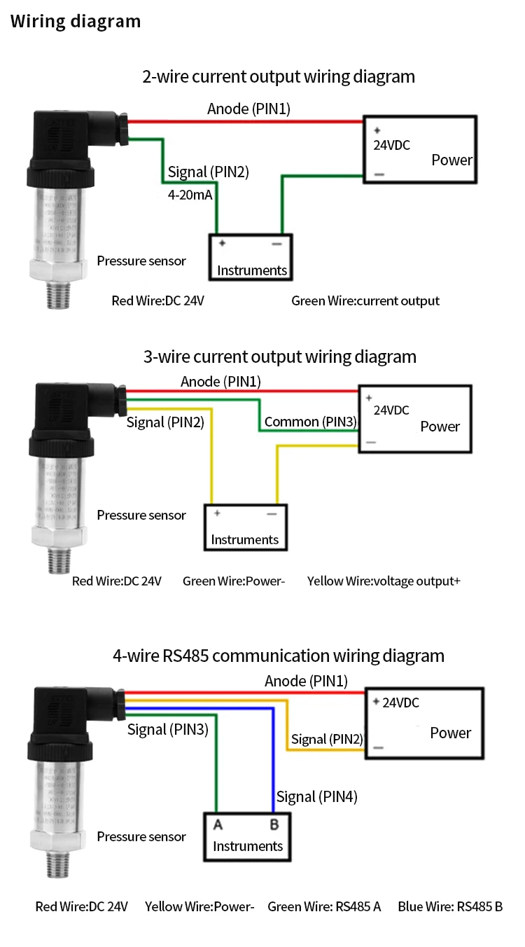
350bar Intelligent Differential Pressure Transducer Transmitter 4 20ma Pressure Sensor - Buy Intelligent Pressure Transmitter,4 20ma Pressure ...
PDF INSTALLATION | WIRING GUIDE - Instrumart Submersible Cable Wire 4 Connector Wiring DIN (Form A, Form C) 5 Bendix™ (6 Pin, 4 Pin) 6 Packard™ Metri-Pack 150 7 Minifast™ and M12x1 8 DT04 DEUTSCH (6 Pin, 4 Pin) 9 Molex™ 10 Pressure + Temperature Transmitter Wiring Cable or Wire (Pressure & Temp.) 11 DIN Connector (Pressure & Temperature) 12
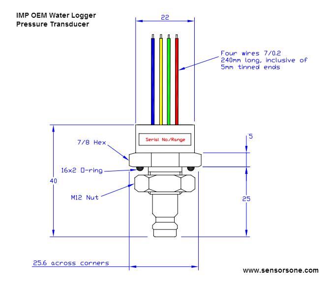
PDF Pressure Sensors and Gauges - AutomationDirect PSD25 Wiring Diagrams Cable Assembly Wiring Colors: Pin 1 - Brown Pin 2 - White Pin 3 - Blue Pin 4 - Black Note: wiring colors are based on AutomationDirect CD12L and CD12M 4-pole PNP cable assemblies. PSD25 Series Pressure Switches See our website for complete Engineering drawings. tPRS-2 Pressure Sensors and Gauges 1 ...
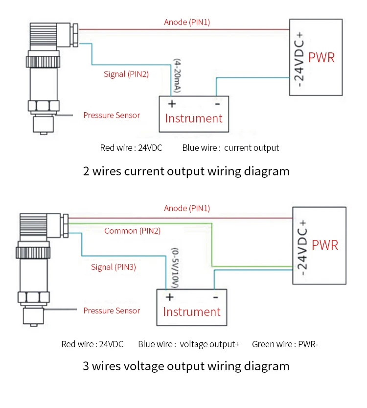
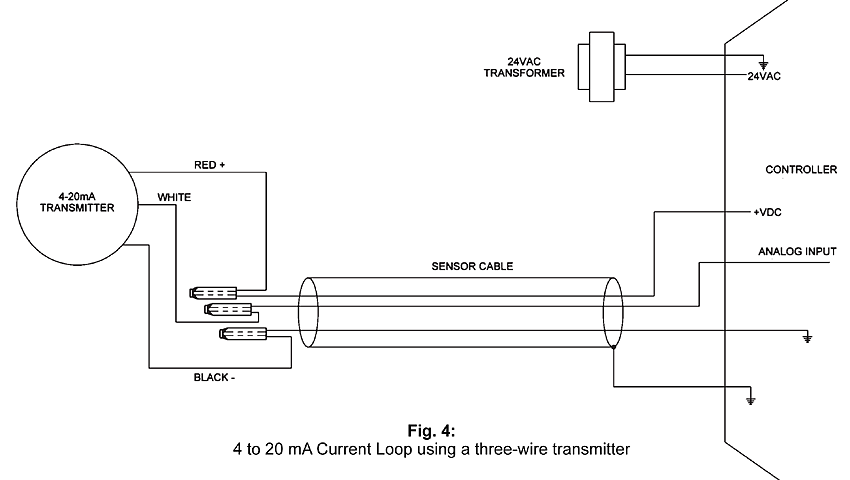
4-20 mA Transmitter Wiring Types : 2-Wire, 3-Wire, 4-Wire 4-20 mA Transmitter Wiring Types : 2-Wire, 3-Wire, 4-Wire. Transmitters are available with a wide variety of signal outputs. The 4-20mA analogue signal is by far the most commonly used in industrial applications. Several physical 4-20mA wiring options exist. This guidance note aims to outline these options.
2 Wire Pressure Transmitter Wiring Diagram - easywiring A wiring diagram is a streamlined standard pictorial depiction of an electric circuit. 2 wire pressure transducer wiring diagram 4 20ma transmitter circuit diagram awesome 3 wire pressure transducer wiring diagram. All devices in a 4 20 ma current loop need to be supplied power from somewhere in order to function.
4 - 20mA Transmitter Wiring Types: 2 -Wire, 3 - Wire & 4 ... Today's electronic process transmitters - pressure, temperature, flow and level are connected in different wire types or configurations. These connection methods are of great concern to the instrument engineer/technician. The 2 - Wire, 3 - Wire and 4 - Wire types are often used to describe the method of connection of electronic transmitters.
4 Wire Wiring Diagram - easywiring A 4 wire transmitter has 2 wires connected to a power supply and 2 signal wires connected to the plc. For complete instructions on wiring a basic 4 way switch see our wiring a 4 way switch article. To view it at full size click on the diagram. In this circuit there are three leads coming from the rtd instead of two.
4-20mA hydraulic/air pressure sensor wiring - YouTube ATO pressure sensor is suitable for water, oil, gas pressure and other environments, and its output 4-20 mA signal can be used in various industrial equipmen...
Pressure Sensor & Wiring Diagram - YouTube Pressure Sensor & Wiring DiagramAmazon Printed Bookshttps:// Kindle Editionhttp:// ...
Diagram 2, 3, 4 - wire transmitter working principle and ... 4 wire transmitter wiring diagram The figure above shows the wiring diagram of the four-wire transmitter. Most of the power supply is AC 220V, and some are DC 24V. DC4 ~ 20 ma output signals and the load resistance is 250 Ω, or DC0-10 ma, load resistance to 0-1.5 K Ω; Some also have mA and mV signals, but the load resistance or input resistance,
4-wire Transmitters Current Loops - InstrumentationTools These transmitters are called "4-wire" or "self-powered" units. The current signal from the transmitter connects to the process variable input terminals of the controller to complete the loop: Note : Here in this article, we are assuming a simple microcontrollers based controllers is connected with a 4 wire transmitters.

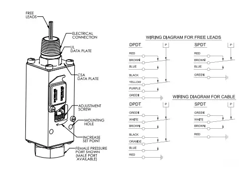


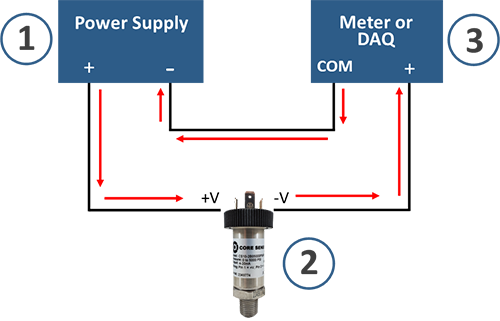











0 Response to "37 4 Wire Pressure Transducer Wiring Diagram"
Post a Comment