36 submersible pump installation diagram
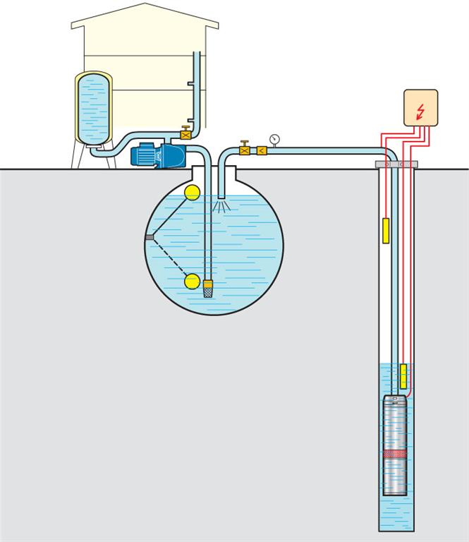
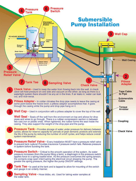
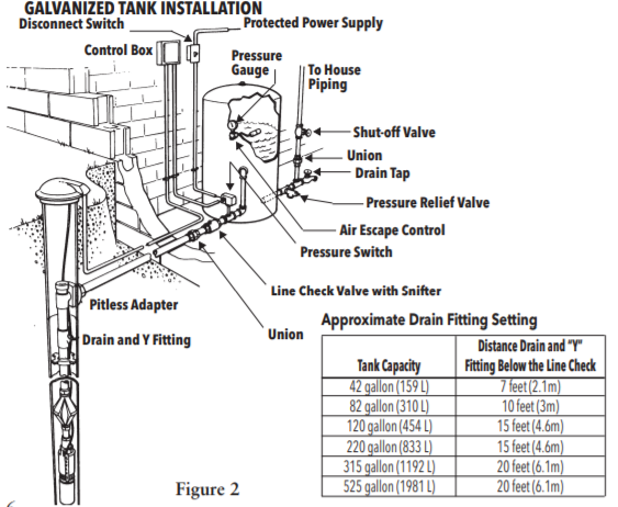
pump installation when the pump is idle. 8. Tank Tee Connets water line from pump to pressure tank and service line from tank to house. Taps are provided to accept Pressure Switch, Pressure Gauge, Drain Valve, Relief Valve, Sniffer Valve, etc. 9. Drain Valve Drain easy draining of the system. 10. Relief Valve Protects against pressure build-up. Pump Tips, do's and dont's for pumps and pump systems Web www.pumpfundamentals.com ... For deep wells (200-300 feet) a submersible multi-stage pump is required. They come in different sizes (4" and 6") ... You should have the P&ID diagram and understand the reasons for all the devices included in your system.
2 Wire Submersible Well Pump Wiring Diagram - 2 wire submersible well pump wiring diagram, Every electrical arrangement is composed of various diverse components. Each component should be placed and connected with different parts in specific manner. Otherwise, the structure won't function as it should be.

Submersible pump installation diagram
In this video, I go over the differences of a 2 wire and a 3 wire submersible well pump.This is associated with the starting components for the pump and whet... How to adjust the pump pressure control switch using the Square-D Pumptrol™ as an example: This article describes how to adjust building water pressure by setting the water pump cut-in and cut-out pressure on the well water pump pressure control switch. We explain which adjustment nuts to turn and in which direction to change pump cut-in pressure or cut-our pressure settings. Dual Capacitor Wiring Diagram. Installing Profile Seals. Installing 8 Inch and Larger Profile Seals. Multiple Seal Probe Wiring. Panel Wiring Markers. PMR5 Installation Instructions. Seal Probe Installation. Seal Probe Wiring. Single Phase Start Up Check List. Single Phase Pump Capacitor Sizing Procedure
Submersible pump installation diagram. Submersible well pump wiring diagram. Here is the complete guide step by step. Assortment of submersible pump control box wiring diagram. It shows the elements of the circuit as simplified forms and also the power as well as signal links between the devices. For proper installation in a submersible pump application, you must strip 1/4" of insulation from the wire. The heat shrink tube is then slid over one end, the wires insert into the stakon connector. The heat shrink is then crimped to attach the stakon to the wire. Before you shrink the tube, ensure the tube is centred over the stakon connector. Diagrams --Typical Pump Installations. The information provided here is for educational purposes only. Technically qualified personnel should install pumps and motors. We recommend that a licensed contractor install all new systems and replace existing pumps and motors. Failure to install in compliance with local and national codes and ... Name: single phase submersible pump starter wiring diagram - Single Phase Submersible Pump Starter Wiring Diagram Pdf - buildabiz; File Type: JPG; Source: suaiphone.org; Size: 248.97 KB; Dimension: 1161 x 610
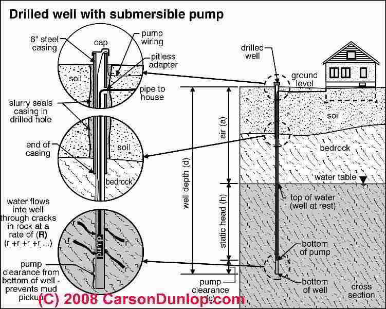
Submersible Well Pump Wiring Diagram - 2 wire submersible well pump wiring diagram, 3 wire submersible well pump wiring diagram, 4 wire submersible well pump wiring diagram, Every electric arrangement is made up of various diverse parts. Each part should be set and connected with other parts in specific manner. If not, the arrangement won't work as it should be. Install a Submersible Pump Lesson#4: Follow These Tricks for Lowering a Submersible Pump Using a grinder to remove the sharp burr on the top edge of a steel well casing. Getting pipe and pump and wires into the well in one piece is heavy work, and there are a couple of things you can do to make success more certain. 3. Pump and pressure main sizing including system curves for initial pump installation and ultimate size pumps. Minimum pressure main size is four (4) inch diameter. Minimum velocity at design pump rate is 2 feet per second. 4. Uplift or buoyancy potential of wet well. The minimum factor of safety is 2.0. C. Catalog cut sheets 1. Structures. 2. The following figure shows schematic diagram of a submersible pump installation: Components of an Electrical Submersible Pumping System (source: API RP 11S3) The Pump discharge head: The pump discharge head is usually a separate component that bolts onto the top of the pump section. Occasionally, the pump is built in either an upper tandem or ...
LANCASTER PUMP recommends an experienced water-well serviceman to install new water systems or replace an existing submersible water-well pump or pump motor ... Water Source Submersible Well Pump Wire Compression Splice Kit-Sk320 - Submersible Well Pump Wiring Diagram. Wiring Diagram consists of several detailed illustrations that present the link of varied products. It contains guidelines and diagrams for different kinds of wiring techniques as well as other products like lights, windows, and so on. PMR5 Installation Instructions. Single Phase Start Up Check List. Seal Probe Installation. Single Phase Pump Capacitor Sizing Procedure. Capacitor Sizing Chart. Installing Profile Seals. Single Capacitor Wiring Diagram. Dual Capacitor Wiring Diagram. GRP Lifting Handle. 208V Operation of HOMA Pumps 3 Phase Submersible Pump Wiring Diagram With Dol Stater Submersible Pump Submersible Pumps 18 Franklin Electric Wiring Diagram Submersible Well Pump Jet Pump Well Pump A Guide Of Auxiliary Contact S And It 39 S Uses And Working In Contactor X2f Motor State Submersible Pump Home Electrical Wiring Electrical Circuit Diagram 3 Phase Dol Starter […]
Diagram showing submersible pumps installation structure ...
Submersible pump installation and repair. Do-it-yourself for a shallow (less than 75ft) well. Need some moderate upper body strength. A helper is nice to p...
The advantages of frequency drive operation in submersible ...
3 Wire Submersible Pump Wiring Diagram wiring diagram is a simplified standard pictorial representation of an electrical circuit. Diagram two wire submersible well pump diagram full version hd quality pump diagram. Submersible well pump wiring diagram for 2 wire submersible well pump wiring diagram image size 290 x 430 px and to view image ...

Submersible Well Pump Accessories Installation Diagram
The wiring connection of submersible pump control box is very simple. 220v 3 wire well pump wiring diagram. Red and yellow might indicate that it is a 2 wire 220 volt pump. 2 wire well pump diagrams are slightly easier to understand and are more straight forward to wire. Electrical ac dc 3 wire 240v for well pump i have a 220v water well pump ...
Soft Starter Function 5.5kw 7.5hp 5500w Pv Solar Pump ...
A leading Manufacturer of quality products for residential and light commercial water systems, sewage, effluent, sump pump, water filtration, and treatment systems. Lead-free and stainless products for every application.

Clean Well Water Report: Well Pump & Pressure Tank Diagram
Wiring Diagram For 220 Volt Submersible Pump Water Pumps Submersible Submersible Pump. Direct On Line Dol Wiring Diagram For 3 Phase With 110 230vac Control Circuit Electrical Circuit Diagram Circuit Diagram Electrical Wiring Diagram.

What is a Submersible Pump? | How does a Submersible Water ...
The Red Jacket submersible turbine pump (STP) is engineered for advanced environmental protection, serviceability, safety, and flow. The Red Jacket STP fits 4-inch NPT threaded, thin-wall risers and is available in a

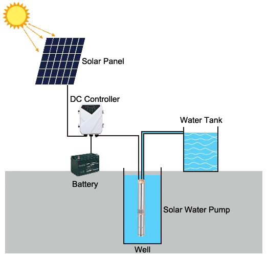
Grundfos SQFlex Solar Water Pump Wiring Diagram
ARKSEN© Deep Well Submersible Pump + Control Box, 1 HP, 110v, 60hz, 33GPM, 200FT Head, Stainless Steel, 4″ 1hp Submersible Bore Water Pump gives you a class-leading flow rate 200ft max head, 33GPM Max flow, impellers to provide stable and remarkable performance High efficiency, hermetically sealed motor is thermally protected to prevent ...
HALLMARK INDUSTRIES INC. Deep Well Submersible Pumps ...
Safe Installation of Submersible Pump. Installation of a submersible pump is a challenging physical task because the pump, wires, and piping need to be lowered to the depth of the well. The persistent issues associated with the submersible pumps often cause severe problems.

How to wire a microswitch tap and water pump | Off-Grid Camper
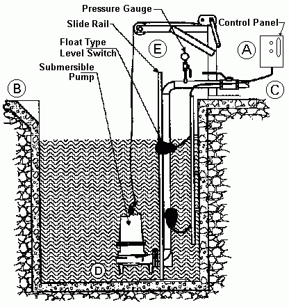
TYPICAL SUBMERSIBLE PUMP INSTALLATION 1. We recommend the captive-air style pressure tank. It has significantly higher drawdown than a standard pressure tank and eliminates water logging problems. The air level in the tank should be 2 lbs. less than pressure switch turn-on level. For a 30-50 switch, this would be 28 lbs. of air with the tank ...

Submersible pump in discharge tube | KSB
INSTALLATION DIAGRAM - SURFACE PUMPS ELECTRICAL CONNECTIONS NOT SHOWN ON THIS DIAGRAM. UNIT MAY BE MOUNTED DIRECTLY ON THE SURFACE PUMP OR BETWEEN THE PUMP AND THE FIRST TAP. 17 Remove pressure switch from surface pump and wire Mascontrol directly to pump.® IMPORTANT INSTALLATION DIAGRAM - SUBMERSIBLE PUMPS
120W 24V DC Solar Water Pump
grundfos submersible pump wiring diagram - What's Wiring Diagram? A wiring diagram is a kind of schematic which uses abstract pictorial symbols to show all of the interconnections of components in a very system.

How to DIY a Sump Pump Installation in Your Basement — Bob Vila
Typical pumps used in a submersible pump installation are either a two or three wire pump. The two wire pumps have the starting capacitor built into the submersible motor whereas the three wire pumps do not have the capacitor built into the motor, they require a control box which is normally found in the pump house at the well head.
VALCO S.r.l. - Installation scheme for submersible multistage ...
Submersible Well Pump Accessories Installation Diagram. This illustration is for educational purposes ; It is not intended as an installation guide.
Deep Well Submersible Pumps Operating & Installation Instructions
Franklin Electric Submersible Pump Wiring Diagram wiring diagram is a simplified all right pictorial representation of an electrical. Thanks for visiting our website to search Submersible Pump Control Box. Same Day Shipping 4 Locations. Diagram two wire submersible well.

Conventional Pump & Pressure Tank Installation Diagram ...
Franklin submersible motors are designed primarily for operation in the vertical, shaft-up position. During acceleration, the pump thrust increases as its output head increases. In cases where the pump head stays below its normal operating range during startup and full speed condition, the pump may create upward thrust.
Submersible Pumps - RA Mueller
Before Installation. Well pump installation can be dangerous when dealing with water and electricity, so extreme caution must be taken. Before getting started, look up your owner's manual and read over the precautions and all other warnings before beginning the installation. The manual will contain important safety precautions, wiring diagrams, tools required for assembly, proper grounding ...
Submersible Well Pumps Service | Tri County Pumps | MD, VA. WV
Wiring Diagram For 220 Volt Submersible Pump Submersible Pump 1993 Ford Mustang Wiring Diagram 2001 Ford Mus Submersible Pump Submersible Well Pump Sump Pump . How To Wire Contactor And Overload Relay Contactor Wiring Diagram Electrical Online 4u Electrical Circuit Diagram Diagram Electrical Wiring Diagram .

Submersible Pump Control Box Wiring Diagram For 3 Wire Single ...
Submersible Pump Accessories; Unions, Valves and Flange Sets. Grundfos NB(E) and NK(E) ... The diagram below shows you the placement of a central heating pump in a central heating system. ... left or right of the pump offering versatility and accommodating a range of …
How to Install and Wire a Well Pump - Well Pump Installation ...
Deep Well Submersible Pumps. Operating & Installation Instructions. CAUTION: Before operating or installing this pump, read this manual and follow all ...12 pages
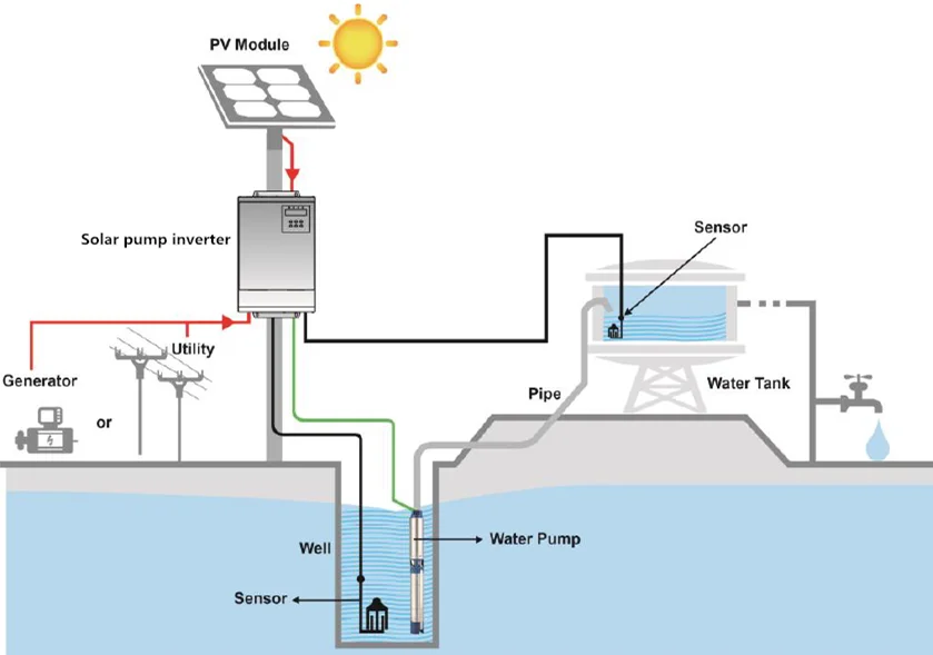
Design Selection and Installation of Solar water Pumping ...
Dual Capacitor Wiring Diagram. Installing Profile Seals. Installing 8 Inch and Larger Profile Seals. Multiple Seal Probe Wiring. Panel Wiring Markers. PMR5 Installation Instructions. Seal Probe Installation. Seal Probe Wiring. Single Phase Start Up Check List. Single Phase Pump Capacitor Sizing Procedure

Hitachi WTP100XS: Automatic Water Pump, Power 100W, Head 14mH, Flow 30L/min, Inlet x Outlet 3/4" x 3/4", 15kg
How to adjust the pump pressure control switch using the Square-D Pumptrol™ as an example: This article describes how to adjust building water pressure by setting the water pump cut-in and cut-out pressure on the well water pump pressure control switch. We explain which adjustment nuts to turn and in which direction to change pump cut-in pressure or cut-our pressure settings.
How Does it Work? • Water Commander™ Backup Sump Pump
In this video, I go over the differences of a 2 wire and a 3 wire submersible well pump.This is associated with the starting components for the pump and whet...

Water Pump Installation and Sales
Wire a three wire 120v well pump directly into pressure ...

ECO-FLO EFSUB5 4 Inch Submersible Pumps Owner's Manual - Manuals+
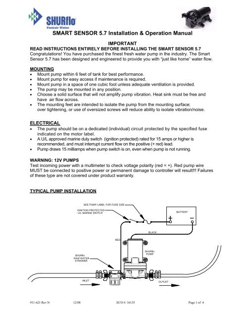
SMART SENSOR 5.7 Installation & Operation Manual - SHURflo
Basement Watchdog Backup Sump Pump System Installations ...
Well & Septic Systems Diagnostics - Monticello Well Pump Services

Submersible Pump - an overview | ScienceDirect Topics

Typical Electrical Submersible Pump system and main ...
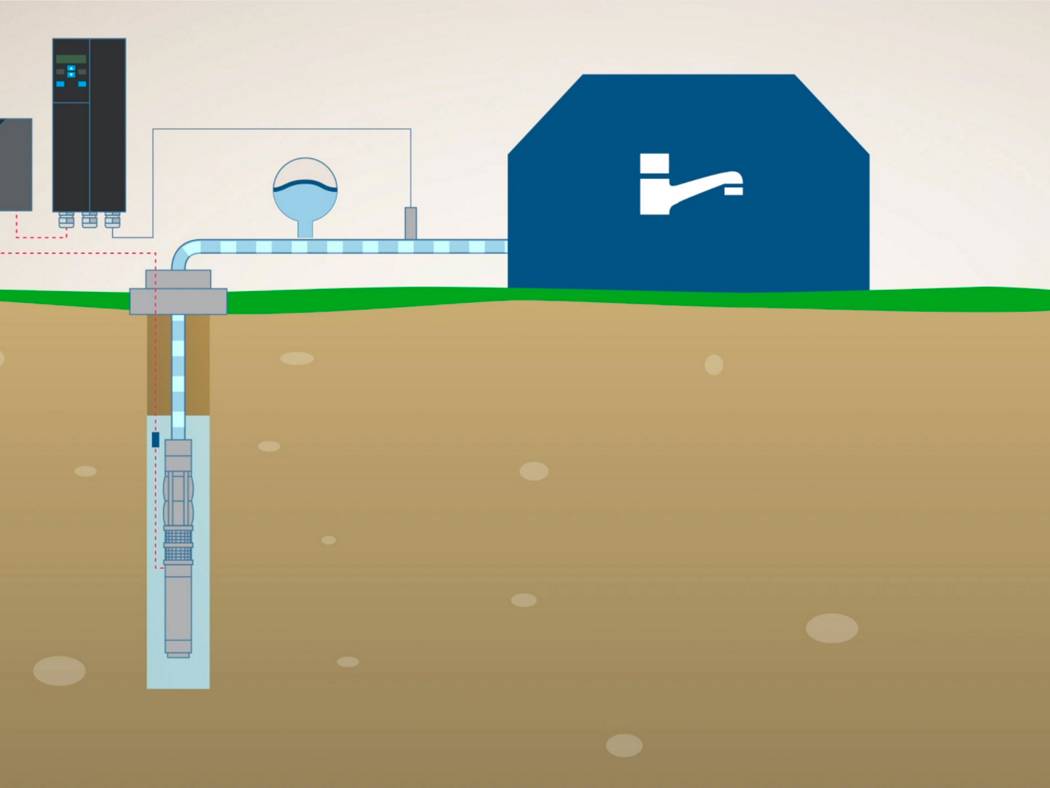
How Does a Submersible Well Pump System Work?

Submersible pump Wiring diagram Control panel Pumping Station ...

Deep Well Pump Installation Diagram | Deep well pump, Well ...

Pedrollo MCm10I Submersible Sewage Pump Single Phase Pedrollo ...
Goulds GS Series Submersible Well Pumps Buyer's Guide & Review
How to Install and Wire a Well Pump - Well Pump Installation ...
0 Response to "36 submersible pump installation diagram"
Post a Comment