35 hydraulic brake system diagram
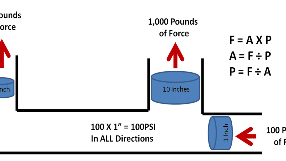
Hydraulic brake is a type of braking system which is widely used in the automobiles with the application of the hydraulic fluid. The working principle of hydraulic braking system is purely based upon Pascal's law, which states that the intensity of pressure exerted inside a closed system by the liquid is always equal in all the directions. Home / Diagrams / Diagram: 2019 CFMoto CFORCE 600 CF600AU-L - BRAKE SYSTEM(WITH HYDRAULIC DISTRIBUTION VALVE - SUMITOMO PLUG) [F08-1-B] Diagram: 2019 CFMoto CFORCE 600 CF600AU-L - BRAKE SYSTEM(WITH HYDRAULIC DISTRIBUTION VALVE - SUMITOMO PLUG) [F08-1-B] ... Diagram: 2007 CFMoto CFORCE 500-A LWB/07-08 - PLASTIC II [F06] From: $ 0.00 ...
A means of storing hydraulic fluid and minimizing contamination is necessary to any aircraft hydraulic system. These functions are performed by reservoirs and filters. The component which causes fluid flow in a hydraulic system--the heart of any hydraulic system--can be a hand pump, power-driven pump, accumulator, or any combination of the three.

Hydraulic brake system diagram
The line diagram indicates the construction of a power-assisted or vacuums brake as shown below. As the brake pedal is pressed, the fluid pressure causes the upper valve of a control unit to open and lower the valve to close. Use only hydraulic system mineral oil (LHM) to replenish the braking and levelling systems.Do not use brake fluids (Castrol RR363,Universal or any other type).The use of any type of brake fluid, even in very small amounts,will necessitate extensive rectification to the braking and levelling systems.Always ensure when purchasing hydraulic system ... Class 5 to 7 Truck & Bus Hydraulic Brake System Diagnostic Guide 4 Preface Purpose of This Diagnostic Guide The purpose of this diagnostic guide is to assist Class 5 to 7 hydraulic brake repair technicians to more accurately and quickly diagnose the most likely causes of a customer's brake related complaint.
Hydraulic brake system diagram. Hydraulic Brakes Mechanical Brakes • DLH • DCM • DSH • DLM • DH • DM • FSH • H Hydraulic and Mechanical Drum Brakes Maintenance Manual No. 4H Revised 4-96 $2.50. Click on the title on this page to go to the Maintenance Manual Index. mon problems found in a hydraulic brake system. The inspection steps are presented in the order in which they are most easily performed. INSPECTION 1. Look for signs of fluid leakage at connection points as well as around wheel cylinder calipers, the master cylinder and hydrovac. Inspect disc brakes caliper piston boots for tears or ... Taking one wheel's hydraulic brake circuit as an exam- ple, a schematic diagram of a hydraulic braking system is shown in Figure 1. The inlet valve (normally open) and the outlet valve (normally ... 4. The air brake system is used in trucks, buses, trains, etc. 4. Hydraulic oil brake system is used for light vehicles such as cars, light-duty trucks, etc. 5. Air compressor uses a certain amount of engine power. 5. No engine power is used. 6. It is not self lubricating. 6. Hydraulic brakes are self lubricating.
"A hydraulic circuit is a system comprising an interconnected set of discrete components that transport liquid. The purpose of this system may be to control where fluid flows (as in a network of tubes of coolant in a thermodynamic system) or to control fluid pressure (as in hydraulic amplifiers). Principle of the hydraulic system of electro-hydraulic servo press brake Principle of Electro-Hydraulic Synchronous Press Brake (Take the system below 300 tons as an example). Pressure control. Start the oil pump motor. According to the required bending force, the proportional pressure valve (4) controls the two-way cartridge valve (2) to adjust the pressure of the hydraulic system to meet the ... HEAVY-DUTY BRAKE FLUID Some hydraulic brake systems use a non-petroleum-based hydraulic brake fluid such as SAE J1703 or SAE J17021. Other hydraulic systems use petroleum-based brake fluids (mineral oil). It is important to ensure that the correct brake fluid is used in the vehicle brake system and incompatible fluids are not mixed. Figure 27 Simple Hydraulic Power System. Figure 28 Line Diagram of Simple Hydraulic Power System. With an understanding of the principles involved in reading fluid power diagram, any diagram can be interpreted. Figure 29 shows the kind of diagram that is likely to be encountered in the engineering field.
Symbol Of Pump Used In Hydraulic System Circuit Diagram. 3. Hydraulic Motor . A hydraulic motor is a mechanical hydraulic actuator that converts hydraulic energy or hydraulic pressure into torque and angular displacement / rotation. Types Of Hydraulic Motors And Their Symbol Used in Hydraulic Circuit Diagram. 4. Hydraulic Cylinder steps on the brake pedal. If the system is equipped with the optional power park brake, the HCU also supplies the energy to release and control the service and park brakes. The Meritor WABCO HPB system for trucks is illustrated in Figure 1.8. A complete HPB system layout, with hydraulic brake lines, appears in the Appendix. Figure 1.8 Figure 1 ... Check for leaks in the rest of the brake system (hoses, fittings, wheel cylinders, etc.) before removing the Hydrovac for repair or replacement. If the basic hydraulic brake system, the vacuum power system and the Hydrovac are found to be in satisfactory operating condition, the vehicle can be returned to service. equipped with hydraulic brakes, built after August 21, 2006 feature the Meritor WABCO Full Power Brake system. The Full Power Brake system provides better pedal feel, shorter stopping distances, antilock brakes, and traction control. But the Full Power Brake system offers a lot more, like Electronic Brakeforce Distribution to compensate for axle

Hydraulic Brakes - Parts, Working, Diagram, Advantages and ...
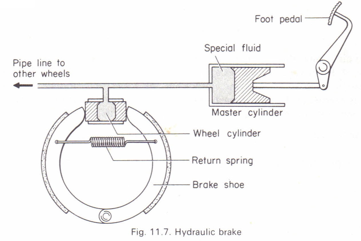
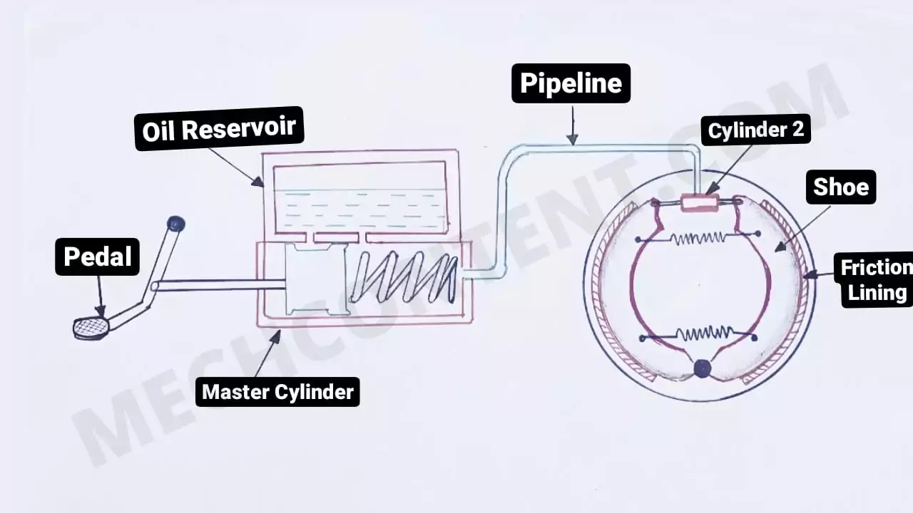
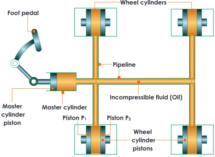
Let’s see the Hydraulic Braking system working in the stepwise:- 1) When the driver presses the brake pedal, the piston presses the oil inside the master cylinder. 2) Oil flows from the master cylinder to cylinder 2 through a pipeline. 3) Now, Oil enters inside the cylinder 2. Hence both piston expands due to oil pressure.
Hydraulic Braking System
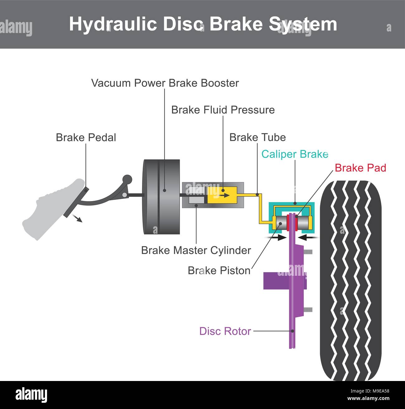
HYDRAULIC DISC BRAKE A hydraulic disc brake incorporates a master piston in the lever, a hydraulic brake line, two or more opposing slave pistons in the caliper, and hydraulic fluid (DOT brake fluid or mineral oil). In a hydraulic brake system, braking is accomplished by actuating the lever, which advances the master piston inside the lever

Tandem Axle Boat Trailer Brake Line Kit 20ft for Hydraulic ...
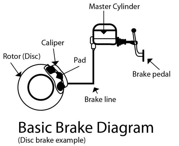
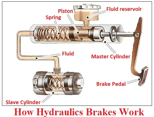
Hydraulic brake. A schematic illustrating the major components of a hydraulic disc brake system. A hydraulic brake is an arrangement of braking mechanism which uses brake fluid, typically containing glycol ethers or diethylene glycol, to transfer pressure from the controlling mechanism to the braking mechanism.
BRAKE SYSTEM DESIGN AND THEORY
Hydraulic Brake Valves The same dependability, safety and performance that goes into every MICO Braking System Product also goes into our versatile, high-performance Brake Valves and Brake Valve Components. This is an important consideration when you select a source of supply for your fluid power needs.
The transmission of pressure in fluids. Hydraulic brake ...
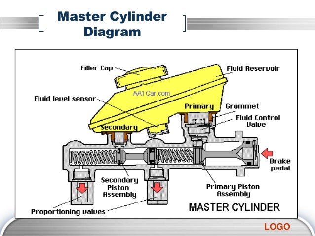
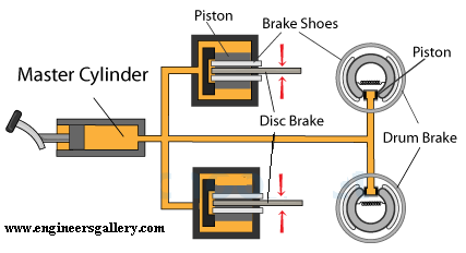
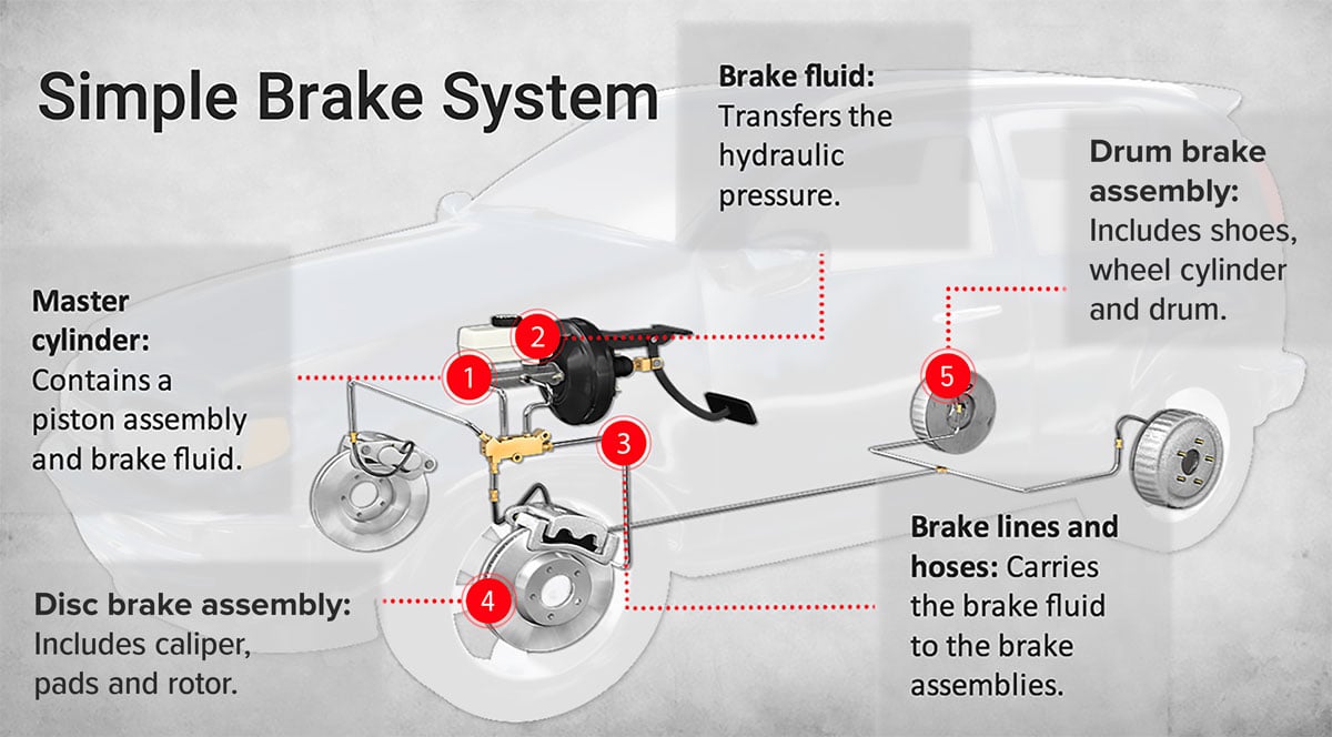
hydraulic braking system diagram The master cylinder is connected to all the four-wheel cylinders by tubing or piping. All cylinders and tubes are fitted with a fluid that acts as a link to transmit pedal force from the master cylinder to wheel cylinders. Brake Fluid The fluid-filled in the hydraulic brake system is known as brake fluid.
BRAKE SYSTEM TYPES AND HYDRAULIC BRAKE PARTS AND FUNCTIONS ...
Common pedal ratios for a manual system are 7:1 or 8:1, and 4:1 or 5:1 for power systems. Ok, lets look at the different things you will find in a typical brake system. MASTER CYLINDER. At the least in a brake system, change to a dual reservoir master cylinder. The master cylinder needs to match your braking system.
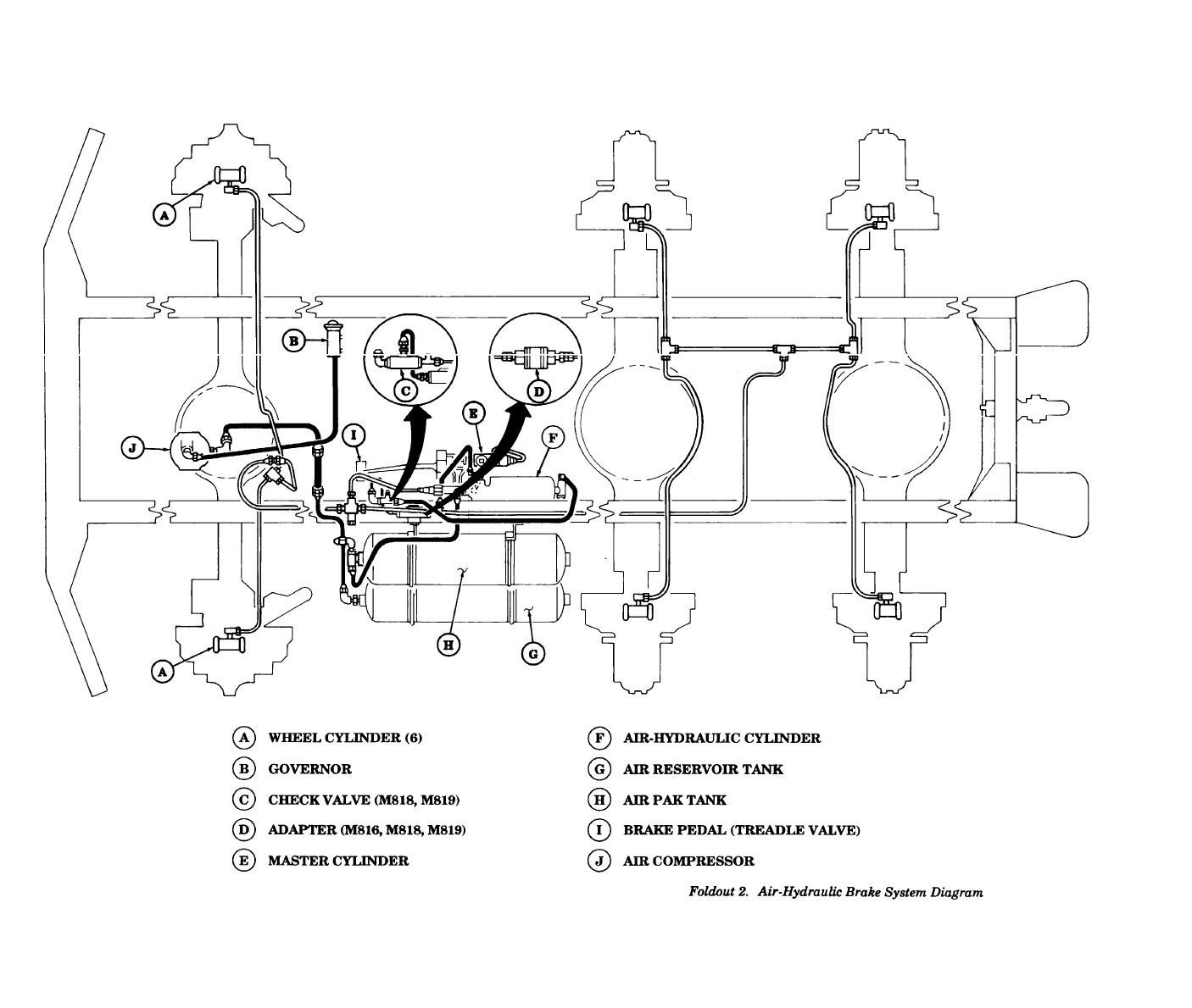
Foldout 2. Air-Hydraulic Brake System Diagram
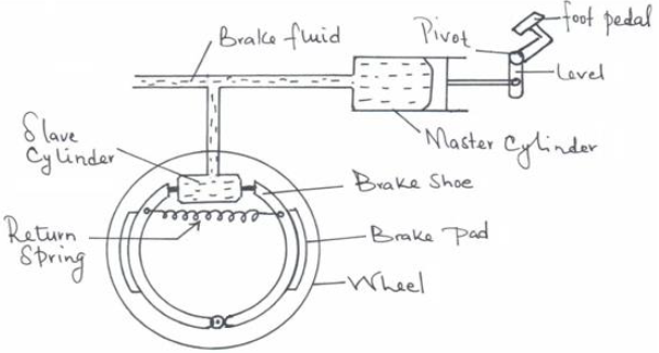
Bleeding? , Brake oil? Yeah right, whenever we face problem with your car’s or bike’s braking system we often hear these terms from the mechanic, and also if we talk about the two wheeler’s disc brakes we only see a hard black color pipe connecting the brake lever with the caliper, we don’t see any mechanical linkage like our bicycles, right? So now the questions arise how these brakes work without any mechanical connection between the actuator (lever or pedal) and the drum shoe or disc caliper? , why do we need brake oil for our braking system? So let’s just dig into this article to find out. Hydraulic braking system is a type of braking system in which unlike the mechanical braking system, hydraulic fluid is used to transmit the brake pedal or brake lever force from the brake pedal or brake lever to the final drum shoes or disc caliper in order to achieve braking. In this type of braking system the mechanical force transmitted by the driver on the brake pedal is converted into the...
DIY Auto Service: How Hydraulic Brake Systems Work - AxleAddict
Brake hydraulic system block diagram . Analytic approaches for keeping high braking efficiency and clamping efficiency of electro wedge brakes. Fig. 1 provides schematic diagrams of a conventional hydraulic brake caliper.2 A hydraulic piston pushes an inner pad.

Brake Operating Systems (Automobile)
brake rotor and caliper. The wheel hub and brake assembly components should be thoroughly wetted to suppress dust before the brake shoes or brake pads are remov Wiped. e the brake parts clean with a cloth. c. If an enclosed vacuum system or brake washing equipment is not availabl e, employers may
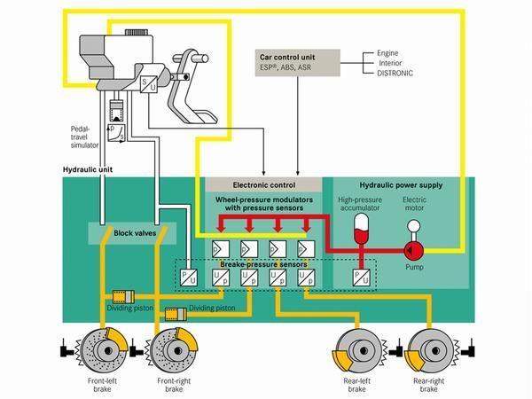
What is electro-hydraulic braking? PH Explains | PistonHeads UK
26 Sept 2020 — Working of drum hydraulic brake system ... In the hydraulic brake type, the actuation of the brake pedal is attached to the piston of a master ...
Basic Brake System Operation
The handbrake gives limited braking if the hydraulic system fails completely, but its main purpose is as a parking brake . The handbrake lever pulls a cable or pair of cables linked to the brakes by a set of smaller levers, pulleys and guides whose details vary greatly from car to car.
The Drive Train, Hydraulic Brake System, Steering System ...
hydraulic brake actuation unit. A typical assembly is shown in Figure 1. The booster reduces the pedal effort required to apply the brakes as compared to a non-power system. General Description Hydro-MaxTM Booster The hydraulic booster is comprised of an open center valve and reaction feedback mechanism, a

Air Brake Basics Part 1
Brake System Diagram - Street Rod. This diagram shows a typical street rod brake system. A 2 PSI residual pressure valve (RPV) is needed in the disc brake circuit, and a 10 PSI RPV is required in the drum brake circuit as well as an adjustable proportioning valve (APV). This diagram illustrates the 2 most common types of fittings used in street ...
Full Power Hydraulic Brake System for Heavy-Duty Vehicles
Class 5 to 7 Truck & Bus Hydraulic Brake System Diagnostic Guide 4 Preface Purpose of This Diagnostic Guide The purpose of this diagnostic guide is to assist Class 5 to 7 hydraulic brake repair technicians to more accurately and quickly diagnose the most likely causes of a customer's brake related complaint.
Hydraulic Braking system: Definition, Principle, Diagram ...
Use only hydraulic system mineral oil (LHM) to replenish the braking and levelling systems.Do not use brake fluids (Castrol RR363,Universal or any other type).The use of any type of brake fluid, even in very small amounts,will necessitate extensive rectification to the braking and levelling systems.Always ensure when purchasing hydraulic system ...
How the Braking system Works in a Car | Car Construction
The line diagram indicates the construction of a power-assisted or vacuums brake as shown below. As the brake pedal is pressed, the fluid pressure causes the upper valve of a control unit to open and lower the valve to close.

Animation | How hydraulic brake works and brake bleeding is done.
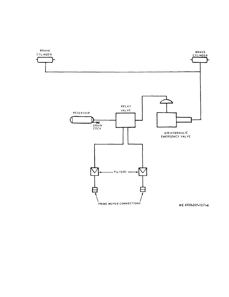
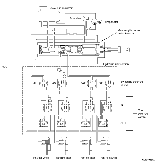
Figure 1-6. Hydraulic brake system schematic diagram.

Hydraulic brake | Car brake system, Hydraulic systems, Car ...
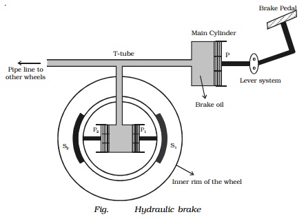
Applications of Pascal's law: Hydraulic lift and brake
HYDRAULIC BRAKE BOOSTER
Hydraulic Brake | Engineers Gallery

Press Brake Hydraulic System: The Ultimate Guide | MachineMfg

Brake System - an overview | ScienceDirect Topics

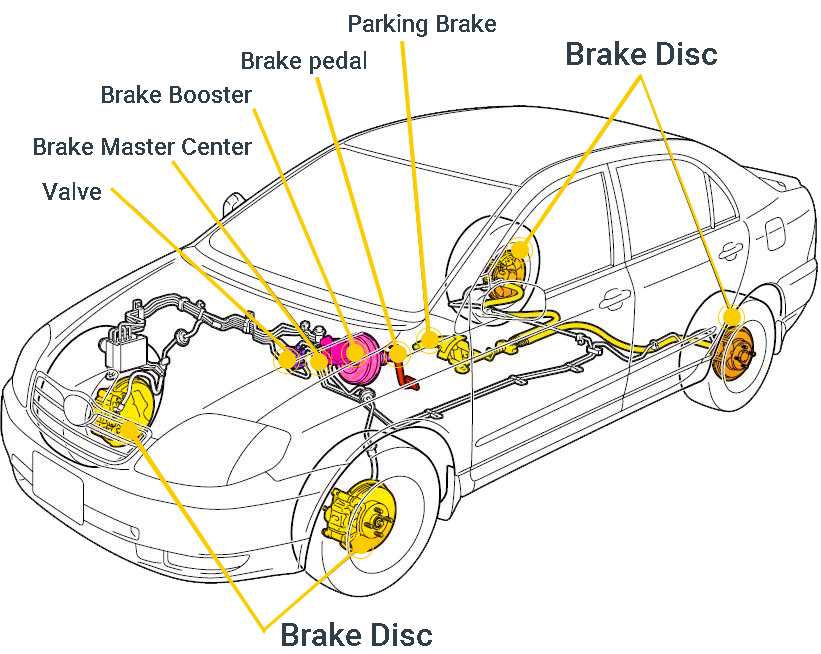
Car Brake System Diagram

Schematic diagram of the hydraulic braking system. | Download ...
Complete Guide to Disc Brakes and Drum Brakes - Les Schwab

Common Brake System Components and Short Descriptions – Rx ...

Mechanical Engineering: Hydraulic Brake
hydraulic brake system, when the brake pedal is pressed, a ...

Hydraulic brake - Wikipedia
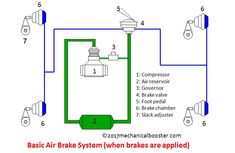
How Air Brake System Works in Automobile? - Mechanical Booster

Explain the Working of a Hydraulic Brake with a Simple ...
The diagram below shows a simplified hydraulic braking system ...
Hydraulic Brakes | Automobilians.com – All About Automobiles
0 Response to "35 hydraulic brake system diagram"
Post a Comment