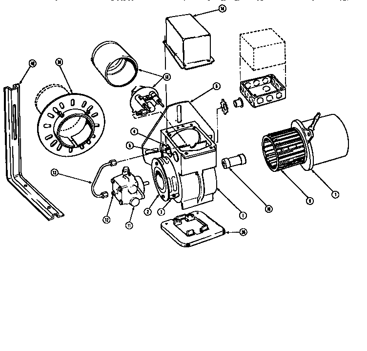
35 beckett oil burner parts diagram
This category contains Burners and replacement parts manufactured by Beckett. Burner Setup—Oil E 3000 Setting the “Z” Distance Prerequisites Burner removed from the machine Beckett T501 gauge Procedure Follow the procedure below to set the “Z” distance on F220 heads. 1. Remove the burner from the machine. 2. Loosen the knurled nut 3. Page 117 E 3000 Burner Setup
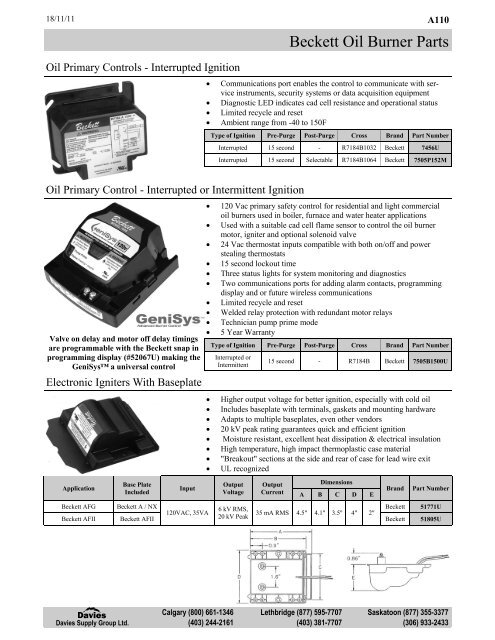
A110 Beckett Oil Burner Parts Davies Supply Group Ltd. Calgary (800) 661-1346 Lethbridge (877) 595-7707 Saskatoon (877) 355-3377 (403) 244-2161 (403) 381-7707 (306) 933-2433 Beckett Oil Burner Parts 28/07/17 A110 Application Input Output Voltage Output Current Dimensions Brand Part Number A B C D E

Beckett oil burner parts diagram
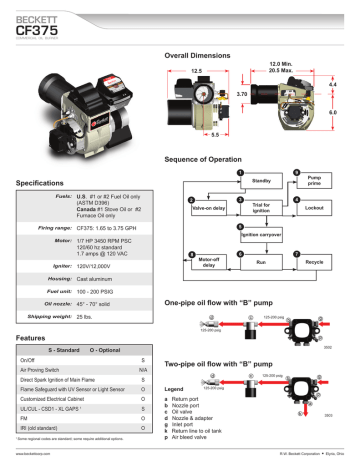
Blower wheel ‘Strip’ construction 3-11/16” Wide Tablock’ Construction 2-1/2” Wide Air Inlet Adapter Inlet Bell Air Guide Air Inlet Shutter 8-Slot 4-Slot Approved Air Tube Combinations “F” Series ONLY “F” or “M” Series Gaskets - Igniter Baseplate/Barrier Optional Required Low Firing Rate Baffle N/A May be specified General Information Oil Burner Specifications – Series EC™ 42.76K: Oil Burner Specifications – Series WBV® 14.03K: Oil Burner Specifications – Series WV-DV™ 33.78K: Residential Oil Burner Specifications : 47.72K: Burner Spec & Data Sheets: Document Title File Size; BSDS – CC™ Beckett CF : 83.51K Part No. Description. 51747. Air Boot Kit Includes: Burner air boot adapter, Vacuum Relief, Inlet air hood. 51851U. Outside air adapter for use with 5207301Uburner cover kit. 51908U. Air Boot Kit – Mobile Home Applications: Air boot, gaskets, instructions. AFII Residential Oil Burner.
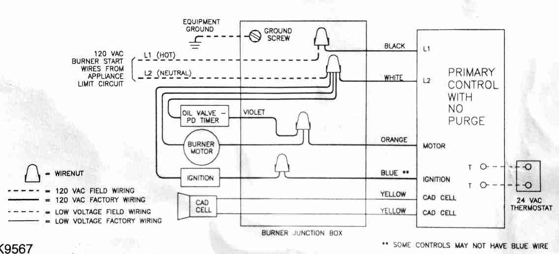
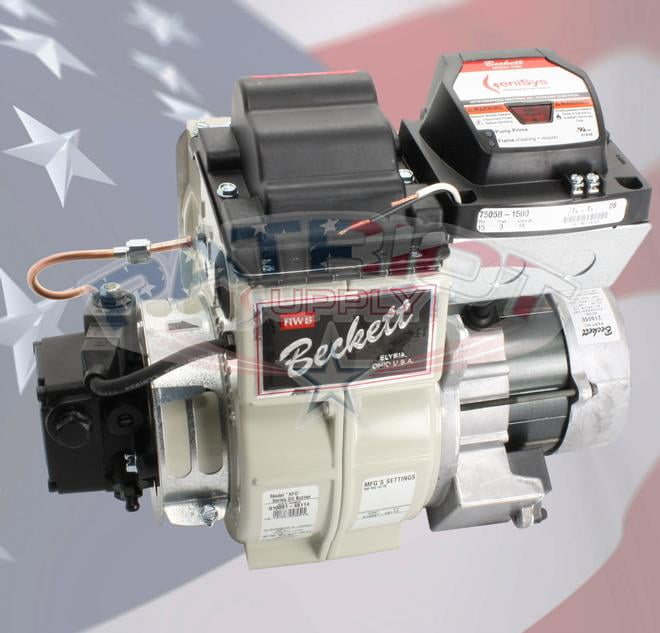
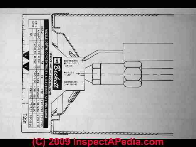
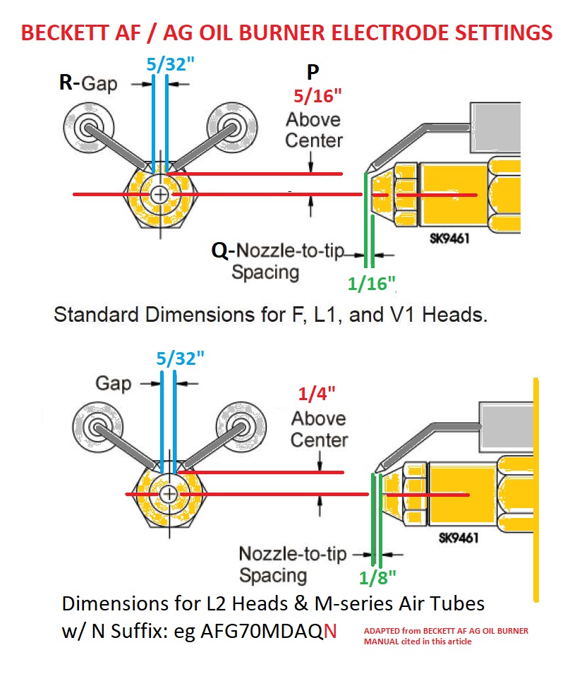
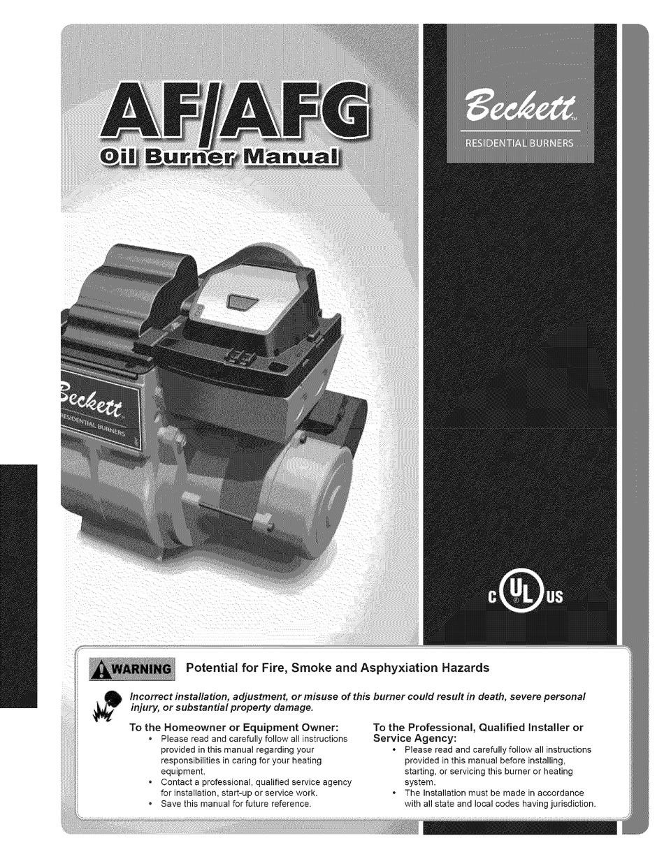
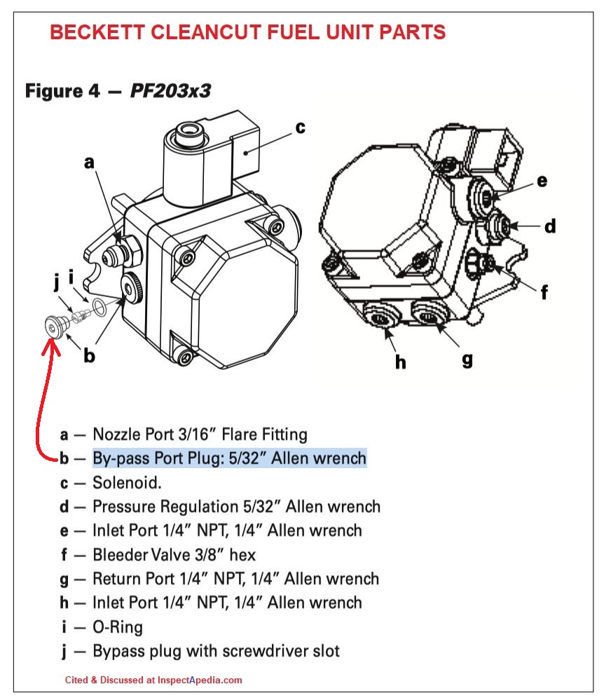
Beckett oil burner parts diagram. Beckett AFG OIL BURNER furnace parts - manufacturer-approved parts for a proper fit every time! We also have installation guides, diagrams and manuals to help you along the way! There are two things which are going to be found in any Beckett Oil Burner Wiring Diagram. The first element is symbol that indicate electric element in the circuit. A circuit is generally composed by many components. The other thing you will find a circuit diagram would be traces. Parts Diagram Beckett Limited Warranty Information This manual contains information that applies to both AF and AFG burners. These burners may appear to be basically identical, but there are differences in design and. Dec 01, · Beckett Oil Burner Pump Filter Parts Diagram ~ This is images about beckett oil burner pump filter parts diagram ... beckett oil burner parts diagram is one of the pics we located on the web from reliable sources. We attempt to talk about this beckett oil burner parts diagram picture in this article because based on info coming from Google search engine, Its one of the top queries key word on the internet.
beckett oil burner parts diagram is among the images we discovered on the internet from reliable resources. We tend to explore this beckett oil burner parts diagram image here just because based on information from Google engine, It really is one of many top rated queries keyword on the internet. 1 Burner input based on No. 2 fuel oil with a heating value of 140,000 Btu per gallon. 2 Net water ratings based on an allowance of 1.15, net steam ratings based on an allowance of 1.333. Consult factory before selecting a boiler for installations having unusual piping and pickup requirements, such as intermittent system operation, extensive piping systems, etc. I have a Burham oil fired boiler model PV84WT-TLWF and need to replace the single wall heat exchanger. Can you provide replacement cost of the coil and provide direction on how to replace it? Tom Says: August 17th, 2014 at 10:37 pm. I have a Burnham oil fired boiler with a Beckett burner and would like a conversion kit to use gas. Beckett Oil Burners & Control Manuals. See our complete list found under "Beckett" in OIL BURNER MANUALS; BECKETT GeniSys™ Model 7505 ADVANCED BURNER CONTROL MANUAL [PDF] Beckett Corporation, USA: P.O. Box 1289 Elyria, OH 44036 Canada: R.W. Beckett Canada, Ltd. Unit #3, 430 Laird Road Guelph, Ontario N1G 3X7 www.beckettcorp.com
Beckett Oil Burner Wiring Diagram September 15, 2020 · Wiring Diagram beckett oil burner wiring diagram – You will need an extensive, expert, and easy to know Wiring Diagram. With this kind of an illustrative manual, you are going to have the ability to troubleshoot, prevent, and total your assignments with ease. 3.2.2022 · B2b kajang prima. Sep 02, 2019 · The furnace should be switched to the "On" position. The REGAL furnaces offer a ceramic fiber combustion chamber and a 10 gauge primary heat exchanger and a 14 gauge secondary heat exchanger, These furnaces have enclosed vestibules with easy to access clean out ports. The World's Longest Diagramless Everything's bigger in Texas. In this diagramless crossword, Acrosses and downs have been merged into a single combined clue list in order of appearance. Rheem/Ruud Gas Furnace Parts. Come search for any parts My HVAC Parts has for Rheem or Ruud products.
Heating aquastat repair: guide to diagnostic troubleshooting for heating boiler aquastat controls: this article describes common operating problems with heating system aquastat controls and how these troubles are diagnosed and fixed. We discuss aquastat problems such as improper adjustment, improper wiring, and relay buzzing or failures.
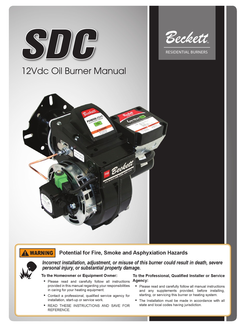
Description : Beckett Burner Model Sdc 12V for Beckett Oil Burner Parts Diagram, image size 723 X 384 px, and to view image details please click the image. Truly, we also have been noticed that beckett oil burner parts diagram is being just about the most popular field right now.
Oil Burner Parts At SuppliesDepot.com, we carry a large selection of oil furnace parts for your home or business. Shop our selection of nozzles, blower motors, primary controls and switches, oil burner motors and oil filters.
Part No. Description. 51747. Air Boot Kit Includes: Burner air boot adapter, Vacuum Relief, Inlet air hood. 51851U. Outside air adapter for use with 5207301Uburner cover kit. 51908U. Air Boot Kit – Mobile Home Applications: Air boot, gaskets, instructions. AFII Residential Oil Burner.
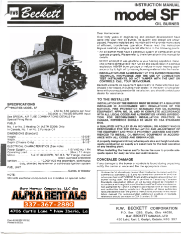
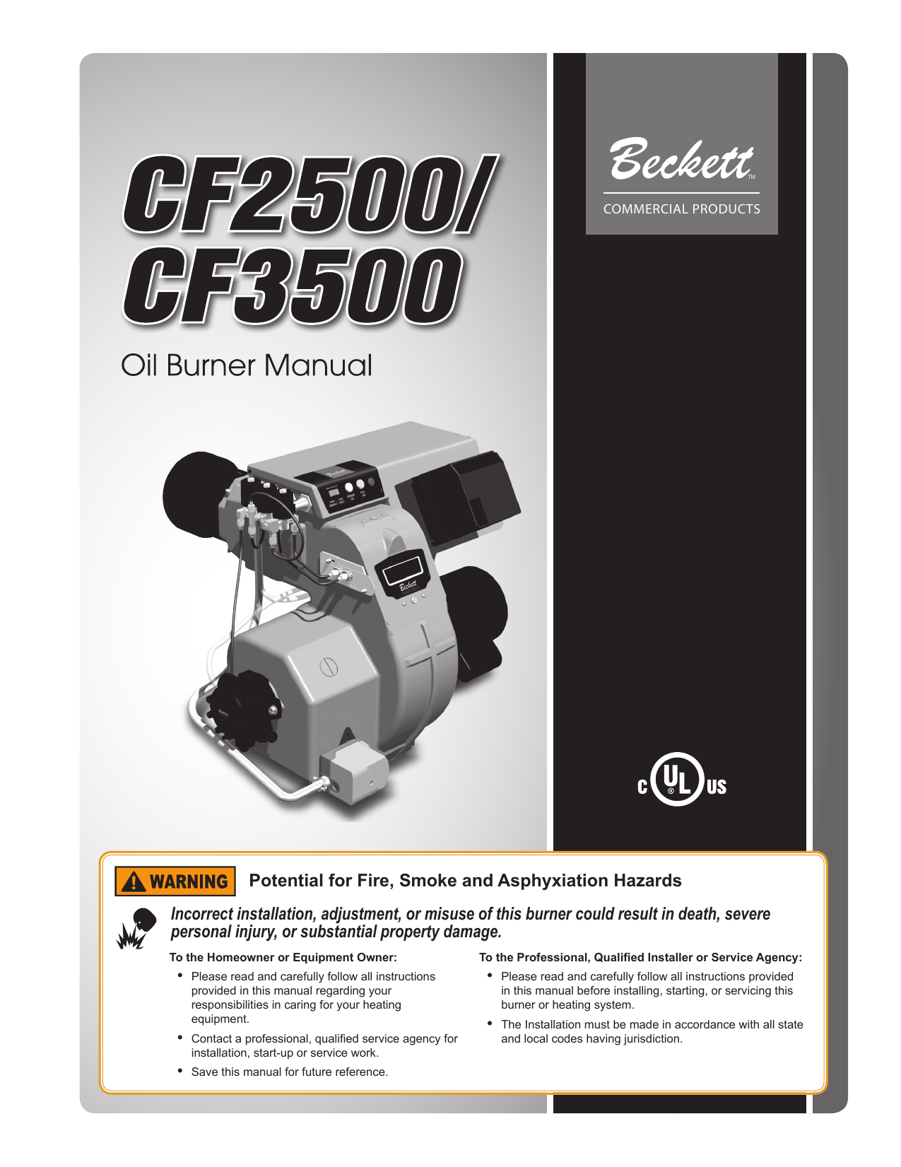
Oil Burner Specifications – Series EC™ 42.76K: Oil Burner Specifications – Series WBV® 14.03K: Oil Burner Specifications – Series WV-DV™ 33.78K: Residential Oil Burner Specifications : 47.72K: Burner Spec & Data Sheets: Document Title File Size; BSDS – CC™ Beckett CF : 83.51K
Blower wheel ‘Strip’ construction 3-11/16” Wide Tablock’ Construction 2-1/2” Wide Air Inlet Adapter Inlet Bell Air Guide Air Inlet Shutter 8-Slot 4-Slot Approved Air Tube Combinations “F” Series ONLY “F” or “M” Series Gaskets - Igniter Baseplate/Barrier Optional Required Low Firing Rate Baffle N/A May be specified General Information











0 Response to "35 beckett oil burner parts diagram"
Post a Comment