37 12vdc to 24vdc converter circuit diagram
12V To 24V DC-DC Converter Circuit. This simple DC-DC converter can provide up to 24V from a 12V source. It can be used to run radios, small lights, relays, horns and other 24V accessories from a 12V vehicle with a maximum draw of about 800mA. It can be used to charge one 12V battery from another, or step up the voltage just enough to provide ... Hi all, I am working on a task to convert 24vac/3A from a transformer giving into 12vdc . This 12vdc will be given to an induction sensor device and to draw a 12v relay. So the current drawn from the circuit wont exceed 200mA. I guess I require a circuit related to LM7812 . since the device to...
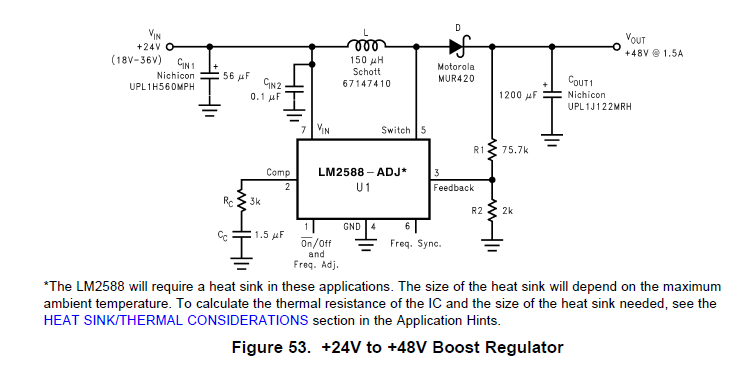
12V to 24V DC DC Converter Circuit. DC-DC converter circuits operating frequency of 40Khz input voltage output voltage of 24 volts to 12 volts and 1.5 amps ...

12vdc to 24vdc converter circuit diagram
DC DC Converter Definition: A DC-to-DC converter is an electronic circuit or electromechanical device that converts a source of direct current (DC) from one voltage level to another. It is a type of electric power converter. Power levels range from very low (small batteries) to very high (high-voltage power transmission). The hardware components required to make 24 V to 12 V converter are: Circuit 1 Circuit 2 Circuit 3 Circuit Operation The schematic appeared in circuit diagram 1 is utilizing an IC, which is named as “LM7812.” LM7812 is a 12 V 1.5 A fixed output voltage regulator IC. 12V to 24V Boost Converter Circuit. Transistor T3 is part of the feedback network and feeds back the output voltage to the gate of the transistor T4, acting when necessary to correct any variation of the output voltage. The output voltage is set using a zener diode D4. The output voltage may be different, if the zener diode is changed to ...
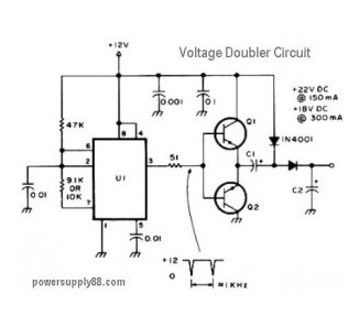
12vdc to 24vdc converter circuit diagram. 12V To 24V DC To DC Converter | Circuit Diagram. The heart of the circuit is a NE555 timer IC that is wired as an astable multivibrator in the circuit. Other components like 1K resistor between pin seven and positive supply, 10K resistor and a 560pF capacitor are used to generate a certain frequency pulses. These frequency pulses are fed to the ... 12V-to-24V Converter Schematic Circuit Diagram. This DC-to-DC converter delivers a maximum power of about 36 watts at an efficiency of 90%. Apart from a modern FET and a Schottky diode, this circuit is comprised entirely of familiar and inexpensive parts. 12VDC. (10.5V to 32V) Immersible 850W or 450W DC/DC converter, 12V to 24V fully isolated. 850W and 450W DC converter with wide range input, 2500VAC isolation and IP67 ingress rating, output voltage is user adjustable between 16V and 28VDC. PSEC-721HS PSEC-621HS. 36 Volts out. 12 Volts (10V to 15V) input. Circuit diagram of 12V to 24V DC DC converter. 12V to 24V dc dc converter circuit. Notes. For L1, I made 60 turns of 22SWG enamelled copper wire on Type No CS166060 Sendust core. The approximate dimensions of the core are as follows. Outer diameter=0.6 inch, inner diameter= 0.3 inch and height=0.25 inch.
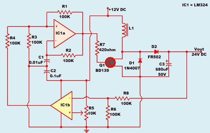
6V to 12V DC Converter Circuits Received by Email - 07/21/2010. Here are some of 6V to 12V DC converter circuits that can be used to convert a small . Car DC Adapter Circuit D Mohankumar - 02/09/2010. Here is a DC adapter to charge Mobile phone or play a Music system using the power from . We called the 555 DC boost converter circuit. To increase the output voltage. There can change in output values. For example, 6VDC to 12VDC converter, 12VDC input to 24VDC output. Here is the step-by-step process. When the input voltages get into IC1-NE555. There is the output comes out of pin 3 at a frequency of 1 kHz. DC-DC Converter 24V to 12V / 20A Circuit Diagram. As shown, the circuit is nothing but an integrated adjustable voltage regulator which is acting on a group of power transistors in parallel. These transistors do the heavy lifting so to speak while the controller is responsible for controlling them. Circuit diagram for 12V to 24V #DCConverter designed using only two op-amps of #LM324. The LM324 is a quad op-amp, which means it has four operational ...
With a battery of 12V, output 24V - 10A and a yield of 90% is the current drawn by 22.2 A. If the battery drops to 10V, current rises to 26.6 A. Source: f6csx.free.fr DC DC Boost Converter Circuit 12V to 24V SG3524 PWM schematic pcb files alternative link: FILE DOWNLOAD LINK LIST (in TXT format): LINKS-4443.zip. The circuit for any buck converter will look very similar to this one. 0. olee5 scd. Reply 6 years ago Reply Upvote. Really thank you for the help!!! 0. RickyD4. 6 years ago on Introduction. Reply Upvote. Your parts list includes a ferrite bead but the part number you have listed is a 10 microH inductor. ... Many times we have the requirements of 24V to 12V converter. The circuits shown below can be used to convert 24V DC to 12V DC. These type of circuits are also called DC to DC converters. You can step down 24V DC to 12V with the help of voltage regulators ICs. The circuit shown in figure 1 is using attached is my schematic diagram. S1 is pin 9 from transformer 74014, and S2 is pin7. when I switch off the 12V DC power supply, the voltage from second output will drop very slowly(0.01VDC~0.02VDC), meanwhile the voltage from first output is drop normal..at the same time, the temperature from IC chip is high.
Simple 12V To 24V DC-DC Converter Circuit Diagram ...
This is the catalog page of the TDK DC-DC Converters. You can find the most suitable product for your design from the catalogs by series. Product Center . ... Equivalent Circuit Model, SPICE Model, Libraries for Simulators of TDK brand components ... 12VDC 24VDC 48VDC. 1.5/3/6/10W. Single Output 3.3 to 12VDC Dual Output ±12VDC.

12v DC to 230v AC cnverter circuit - Electronics Technology
The circuit diagram for 12V to 24V DC Converter is shown below. IC1 LM324 is the core of this circuit. IC1-A, resistors R1, R2, R3, and capacitor C1 forms an oscillator which operates at around 500Hz. R2 and C1 are used to tune the oscillator frequency.

12 volt NiCd battery charger design circuit diagram for ...
12V to 9V DC Converter. This 12V to 9V DC converter is very useful to power 9V DC devices in a car that uses a 12V battery. The maximum current consumption allowed by this circuit is 0.8 amps. This 12V to 9V DC converter is implemented using a zener diode and a NPN bipolar transistor (Q1) as shown in the circuit diagram.

Yellow Porsche 911
Dc To Converters. 12v dc to 220v ac inverter circuit pcb basic schematic for converter diagram pdf power 100w switching transformerless with the 555 voltage working air conditioner 500w using circuits 300watt 24v converters tida 01606 reference design ti com build 200w page 3 supply simple low 1000w sine 13007 phase tidm hv 1ph dcac pure wave solar three 250w 5000w sg3524 230v circuitspedia ...
12vdc To 24vdc Converter Circuit Diagram - General Wiring ...
Hi guys today I'm going to give you 24V to 12V converter circuit diagram.Most of the heavy vehicle drivers asked me about this.Here we have used IC LM 338.With out connecting a heat sink don;t power up the circuit.We hope to give you more 24V DC circuit diagrams.And also this circuit can generate only 5A don't forget it.
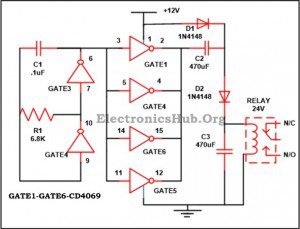
12V to 24V DC Converter Circuit using Hex Inverter IC CD4049
Reaction score. 0. Trophy points. 1,286. Activity points. 1,502. the attached circuit diagram for 24v dc to 12v dc, can i still use it for my 19v dc output by only changing the LM7812 to LM7818 or LM7819, for example. what of the values of the resistor. my load current is 3A. Dec 1, 2010. #11.

Porssche 911 991 GT2RS at Bugatti circuit in Le Mans
Am looking for a circuit that will have an input of 12 volts DC from a sealed lead acid battery and an output of 24 volts AC. I see a lot of circuits that output 110 volts AC but that is to much for what I need. I will be using the circuit to control a single 24VAC Orbit sprinkler valve.

To me, the legendary Porshe Gulf livery is still one of the most iconic in the history of motorsport. This beauty was racing in the WEC 6 hours of Silverstone.
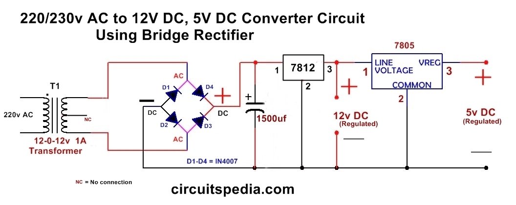
So a 230V AC to 12V DC converter cannot be powered in 110V AC line. To address this isse, an additional setting is provided for different input voltage levels. 2.Despite not having a universal input voltage range, it is a costly choice, as the transformer itself costs more than 60% of the total manufacturing cost of the converter circuit.

12vdc to 24vdc Converter Circuit
So provide input voltage in the range of 3V to 15V. Page 2. Circuit Diagram of 12V to 24V DC Converter: 12V to 24V DC ...3 pages

Kit Converter Dc To Ac - VERTCON
Jan 01, 2021 · So, in this project, we are going to build a simple 12V to 24V DC-DC Converter circuit using NE555 Precision timer IC & a 24V/1W Zener Diode IC. A NE555 timer IC serves as the core of this circuit. The IC possesses an oscillation frequency ranging from 670 to 680 Hz. Here, this NE555 timer acts as an astable multivibrator An astable ...
12V DC Voltage Doubler Circuit - Power_Supply_Circuit ...
12v DC to 24v DC VOLTAGE DOUBLER CIRCUIT | 5v DC to 10v DC | 9v DC to 18v CD | MakeloGy12V to 24V DC Converter CircuitCircuit Components:-- IC CD4049 - 1-- R...
+5v to +12v converter
Aug 09, 2017 · Circuit diagram of step-up DC converter using TDA2004. Next, D2 passes the current to charge into C6. It makes the voltage at pin 10 of IC1/1 is about 0V. But the voltage across C6 or the output equals about the power supply. After that, the output(pin 8) of IC1/2 start to has the voltage rises instead. Because C5 stop charging.

DC Voltage Doubler Circuit +12V to +24V using LM2586 ...
12 To 24V Step-Up Converters. 12-24-18I. Isolated. 12-24-16. Standard Non-Isolated. These "UP" converters produce 24 volts from 12 volt systems and are ideal for managing dual voltage applications on marine vessels without having to install a 24 volt battery and dedicated charging system.
24 V Buck Converter Ic | Free V Bucks Fortnite Pc
This is the circuit diagram of 6V to 12V DC to DC voltage converter (6V to 12V DC voltage doubler). This is the active circuit for voltage doubling from 6 volt to 12 volt DC with 1A maximum current. The IC is used as switcher device. Schematic diagram: Components and its usage: IC Switcher/regulator LM2577T-ADJ… Read More »

48V DC input 12V output step-down circuit |Circuit Diagram ...
Power Inverter 100W, 12V DC to 220V AC . Power Inverter 100W, 12V DC to 220V AC Here is 100 Watt Inverter 12V DC to 220V AC schematic diagram. This circuit designed using the combination of main components IC CD4047, Transistor TIP122 and 2N3055. Circuit Notes: A 12 V car battery can be used as the 12V source. Use the POT R1 to set the …

230vac To 24vdc Power Supply Circuit Diagram
12V to 24V Boost Converter Circuit. Transistor T3 is part of the feedback network and feeds back the output voltage to the gate of the transistor T4, acting when necessary to correct any variation of the output voltage. The output voltage is set using a zener diode D4. The output voltage may be different, if the zener diode is changed to ...

Switched Capacitor Dc Dc Converter - Electronic Diagram
The hardware components required to make 24 V to 12 V converter are: Circuit 1 Circuit 2 Circuit 3 Circuit Operation The schematic appeared in circuit diagram 1 is utilizing an IC, which is named as “LM7812.” LM7812 is a 12 V 1.5 A fixed output voltage regulator IC.

Schematic circuit diagram for 6 Input Mixer - Simple ...
DC DC Converter Definition: A DC-to-DC converter is an electronic circuit or electromechanical device that converts a source of direct current (DC) from one voltage level to another. It is a type of electric power converter. Power levels range from very low (small batteries) to very high (high-voltage power transmission).
30 12vdc To 24vdc Converter Circuit Diagram - Wire Diagram ...

Couple at Werribee Gorge Circuit Track
Technical Page

12V DC to 24V DC Converter Circuit

12v To 24vdc Inverter Schematic - Circuit Diagram Images

GT500

Wiring Diagram PDF: 12v Dc Schematic Wiring Diagram

7 ideas of 555 DC boost converter circuits diagram

12v To 24vdc Inverter Schematic - Circuit Diagram Images

Wiring Diagram: 31 12vdc To 24vdc Converter Circuit Diagram

24V Or 12V To 10V Converter Using LM7810 IC | Circuit Diagram

dc to dc boost converter circuit diagram - Wiring View and ...

Red Porsche GT4 at Circuit Paul Ricard (french track) - 1
12 Volt To 24 Inverter Circuit Diagram - Wiring View and ...
Wiring Diagram: 31 12vdc To 24vdc Converter Circuit Diagram
120VAC to 12VAC/5VDC PSU - CircuitLab
12vdc To 24vdc Converter Circuit Diagram - Free Wiring Diagram

Red Porsche GT4 at Circuit Paul Ricard (french track) - 3

12v To 24vdc Inverter Schematic - Circuit Diagram Images
0 Response to "37 12vdc to 24vdc converter circuit diagram"
Post a Comment