35 powerstat variable autotransformer wiring diagram
I have a Powerstat Variable Autotransformer used. Type 116CU Input V 120 Output V 0 - 140 1 phase. I want a way to test it to see if it works. There are 5 Terminals . I am not electrical at all I just purchased these in a big lot and I need to test them. Thought I would look for help before I blow them up myself. Thanks Terri · The connection diagrams are labeled "L" for Line Connections, "B" for Boost Connections and "S" for Step-Up Connections. · The F236B Series POWERSTAT® Variable Transformers do not have terminals 6 & 7 available and therefore do not have a Step-Up ("S") Connection. Terminal #3 is after the fuse on all F models.
POWERSTAT® Variable Transformers. The flagship voltage control product offered by Superior Electric, POWERSTAT® Variable Transformers provide a simple, rugged method of controlling electrical voltage, current and power. They take in utility line voltage and provide continuously adjustable output voltage. Rugged, and designed for heavy duty ...

Powerstat variable autotransformer wiring diagram
powerstat wiring diagram - What's Wiring Diagram? A wiring diagram is a form of schematic which uses abstract pictorial symbols to exhibit every one of the interconnections of components in the system. PowerStat 1256DT-2S Variable Autotransformer. General Radio W10HG3M 3 Phase Variac. Georator 33-055 Frequency Converter/Motor Generator. Georator 33-184 Permanent Magnet Alternator 400 Hz. Phase Technologies PT020 Phase Converter. PowerStat 136-1057 Variable Transformer. 236B from Superior Electric at Allied Electronics & Automation. Description. Variable Transformer 0.24 V 10A Out 2.4kVA, 240V Vi, Panel, 50/60Hz, Knob
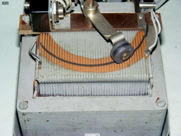
Powerstat variable autotransformer wiring diagram. Variac Transformer Wiring Diagram. A POWERSTAT Variable Transformer is a precision product packed with care. encountered while drilling holes, installing wiring, etc, during installation. . in the tables and diagrams are for motor driven units and units with the knob. The inductor is shaped like a doughnut (toroid) with wire wrapped radially through Unlike a transformer with isolated input and output windings, variacs have a single In the diagram to the left, I've stretched out the toroid ... wiring diagram periodic, powerstat variable autotransformer wiring diagram free, auto transformer starter and variable autotransformer, comparison between dire ct on line star delta and auto, theory of operation autotransformer starter, 3 phase motor starter wiring diagram pdf free wiring diagram, 11 auto transformer A variable voltage autotransformer (also known as variac) is a transformer which is able to transform Variable Voltage Autotransformer Wiring Diagram, Image. The inductor is shaped like a doughnut (toroid) with wire wrapped radially This diagram has 5 terminals, but 3 and 4 terminal variacs eliminate one or two of. Volt-Pac® variable transformers provide continuously adjustable voltage to an electrical load from a fixed line voltage. Operation is based on autotransformer action in unsaturated magnetic components, so the output waveform is a precise reproduction of the input waveform.
on Variac Transformer Wiring Diagram. A variable voltage autotransformer (also known as variac) is a transformer which is able to transform Variable Voltage Autotransformer Wiring Diagram, Image. A POWERSTAT Variable Transformer is a precision product packed with care. encountered while drilling holes, installing wiring, etc, during installation. Sep 03, 2013 · Powerstat Variable Autotransformer Wiring Diagram. Mze electroarts entertainment mzentertainment com dr zee work powerstat 0 120 vac variable transformer variac with output voltmeter monitor project i have a autotransformer type 116cu input v 140 1 phase want way to test transformers superior electric how wire an use can someone explain wiring ... A P01AlEASTAT variable transformer is an autotransformer of toroidal .. Coil to terminal wiring for POWERSTATS of the 10 series is shown in DIAGRAM.Powerstat Variable Autotransformer Wiring Diagram Image. See the All powerstat wiring diagram gallery. Find out more powerstat wiring diagram Photos below: A Newbie s Overview to Circuit Diagrams. Powerstat variable autotransformer wiring diagram An auto-transformer is a nifty device. Unlike a conventional transformer, it only has one winding. This winding is constructed with taps at various points to allow accessing different numbers of turns in the coil….but in a variac, the construction is further enhanced by construction that ...
The little Powerstat unit is 120V (and 60Hz), so is of limited use in a 230V country like Australia. It's still potentially useful of course, once I find a use for it. Figure 2a - Carl Zeiss Variable Voltage Transformer, 2b - Powerstat Panel Mount. The traditional Variac is an autotransformer, and provides no isolation between primary and ... in the tables and diagrams are for motor driven units and units with the knob. I picked up a new powerstat but no wiring diagram. it says Superior electric type input vac output vac Has terminals 1,2,3,4,5 3. Note this is a variable autotransformer. It is NOT ground isolated. 1 - common for input and output 3 - output (wiper) 4 - input 2 ... Good day all. I have a Powerstat Variable Transformer that I picked out of the garbage and have been playing with. Looking at the diagram on the front of it, it appears as though input goes hot to terminal 5, common terminal 2, and terminal three appears to be the varying voltage. May 17, 2021 · Variety of powerstat variable autotransformer wiring diagram. A wiring diagram is a streamlined traditional pictorial representation of an electric circuit. It shows the elements of the circuit as simplified forms, as well as the power and signal links between the gadgets. A wiring diagram typically gives info concerning the relative placement as well as plan of gadgets and also terminals on the devices, to help in building or servicing the device.
SOLVED: Wiring diagram for powerstat type 116 - Fixya
N4AEQ Ham Member QRZ Page. I picked up a new powerstat but no wiring diagram. it says Superior electric type 21: input 120 vac. output 0-140 vac. Has terminals 1,2,3,4,5. 3 is the wiper output. 1 is a input. 5 is tapped 1/3 way from the input. 2 is tapped 2/3 way from the input.
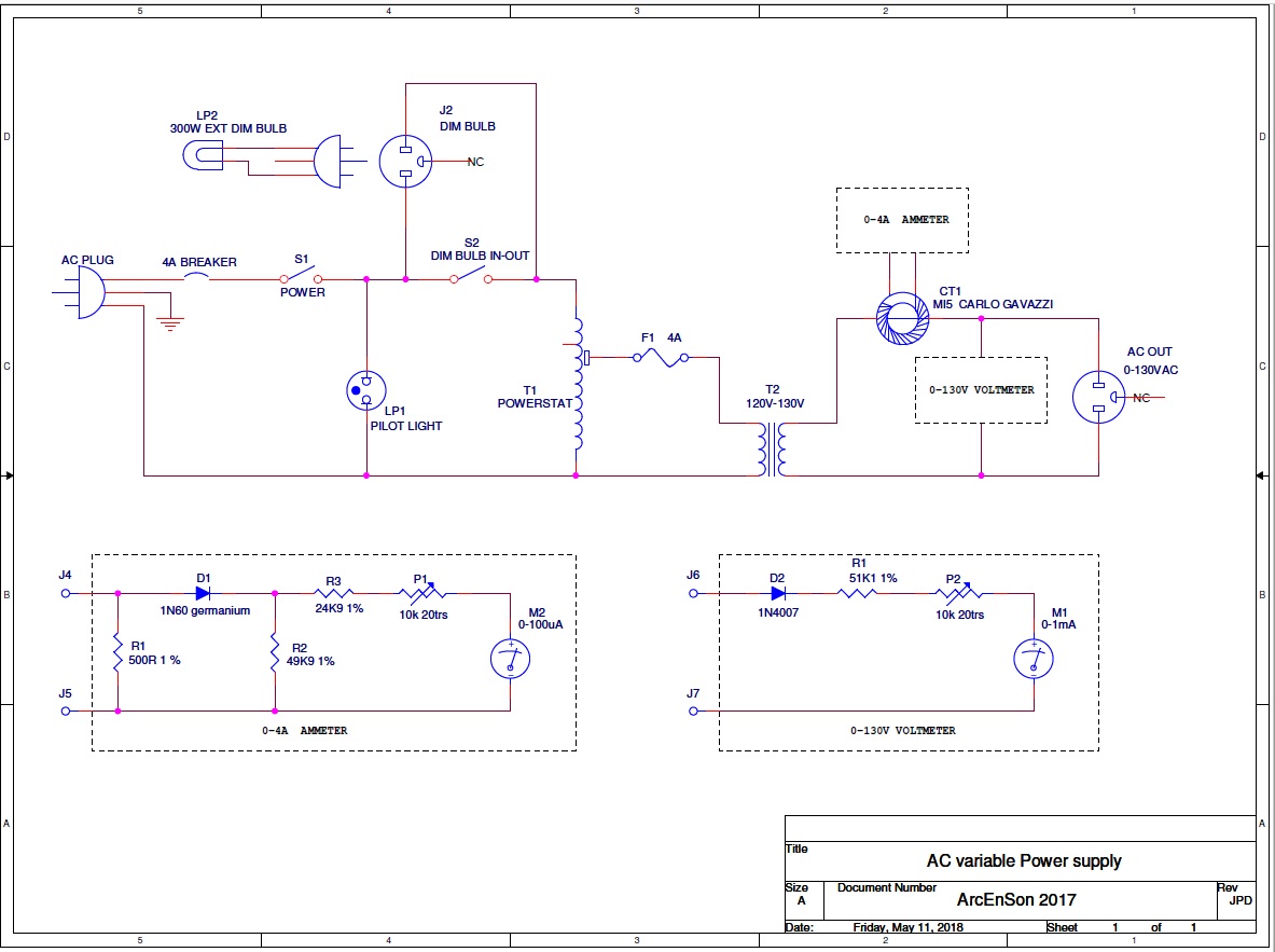
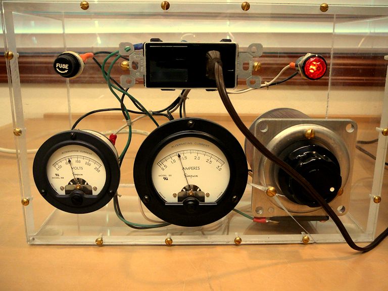
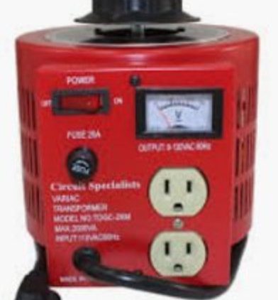
AC Variable Isolated Power Supply
Hi there- What we've got up for grabs today is a Powerstat Variable Auto Transformer(Variac) It's a Type 116B. 1 Phase, 50-60 Hz, input 120V, output 0-140V, 10 amp, 1.4KVA. It was made by the Superior Electric Company of Bristol Connecticut.

POWERSTAT VARIABLE AUTOTRANSFORMER 15 amp - $125.00 | PicClick
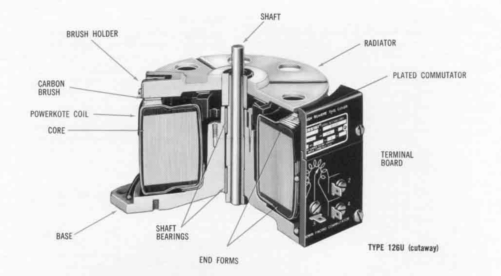
The 246 is a 1-phase POWERSTAT Variable Transformer with rugged mechanical construction. This POWERSTAT transformer features POWERKOTE coils for longer life, increased ratings, greater overload capacities and better resistance to fungus, salt spray and other contaminating atmospheres. The commutator of the new POWERKOTE coil is embedded in a high temperature material which holds the windings ...
Variacs and Their Uses
A POWERSTAT Variable Transformer is a precision product packed with care. ... diagram. 002105-006 REV G. MOTOR DRIVE WIRING. FIGURE H.

Can Someone explain Variac wiring to a dummy? - Pre-1950 ...
POWERSTAT® Variable Transformer -- FR6000 Series The POWESTAT Full Range Regulator Controller is a solid-state sensing device which monitors and detects any variation in load voltage or current and operates a POWERSTAT Variable Transformer synchronous drive...
Auto transformer for Fan - Pre-1950 (Antique) - Antique Fan ...
· The connection diagrams are labeled "L" for Line Connections, "B" for Boost Connections and "S" for Step-Up Connections. · The F226 Series POWERSTAT® Variable Transformers do not have terminals 6 & 7 available and therefore do not have a Step-Up ("S") Connection. Terminal #3 is after the fuse on all F models.

Powerstat 3PN116B Autotransformer Variac 0-140vac 10a ...
Powerstat 116 series, a popular style of buck-boost autotransformer. The big advantage of this, is that unlike a resistance based device, the heat dissipation is low. Additionally, unlike electronic dimmer devices that use SCRs or Triacs, there is no distortion of the waveform. The type of AC wave going in is the type that comes out.

Autotransformer - Wikipedia
May 7th, 2019 - Auto transformer starter and variable autotransformer at wiring diagram Wiring Diagram 3 Phase Auto Transformer Among the automotive repair responsibilities that are hardest a repair or mechanic shop could tackle is the wiring or rewiring of a car's

Variacs and Their Uses
powerstat variable autotransformer wiring diagram. powerstat linux. powerstat 116 wiring diagram. powerstat variable autotransformer 3pn116b. powerstat 3pn116c. Rotation of the brush-tap by either manual or motor-driven means POWERKOTE coii is embedded in a high temperature material 136B-236B Series. powerstat 236b manual muscle Find great ...

SUPERIOR ELECTRIC CO. POWERSTAT 3PN116 120V Variable 0-140 ...
236B from Superior Electric at Allied Electronics & Automation. Description. Variable Transformer 0.24 V 10A Out 2.4kVA, 240V Vi, Panel, 50/60Hz, Knob

Superior Electric Powerstat variable transformer and isolation transformer
PowerStat 1256DT-2S Variable Autotransformer. General Radio W10HG3M 3 Phase Variac. Georator 33-055 Frequency Converter/Motor Generator. Georator 33-184 Permanent Magnet Alternator 400 Hz. Phase Technologies PT020 Phase Converter. PowerStat 136-1057 Variable Transformer.

Powerstat 3PN116B Autotransformer Variac 0-140vac 10a ...
powerstat wiring diagram - What's Wiring Diagram? A wiring diagram is a form of schematic which uses abstract pictorial symbols to exhibit every one of the interconnections of components in the system.
Staco VARIAC 1010, 1020, 1210, 1220 Series Variable Transformers

SUPERIOR ELECTRIC 236B Variable, Manually Operated, Open, Single Phase, 50Hz / 60Hz, 240V, 280V

TECHNIPOWER GENERAL RADIO Variac Staco Powerstat Variable ...
A Deluxe Test Bench Variac | Nuts & Volts Magazine

Superior Electric Co. 146 30 Amp 146 Powerstat variable autotransformer

Powerstat Var. Autotransformer 116B Equipment Superior ...
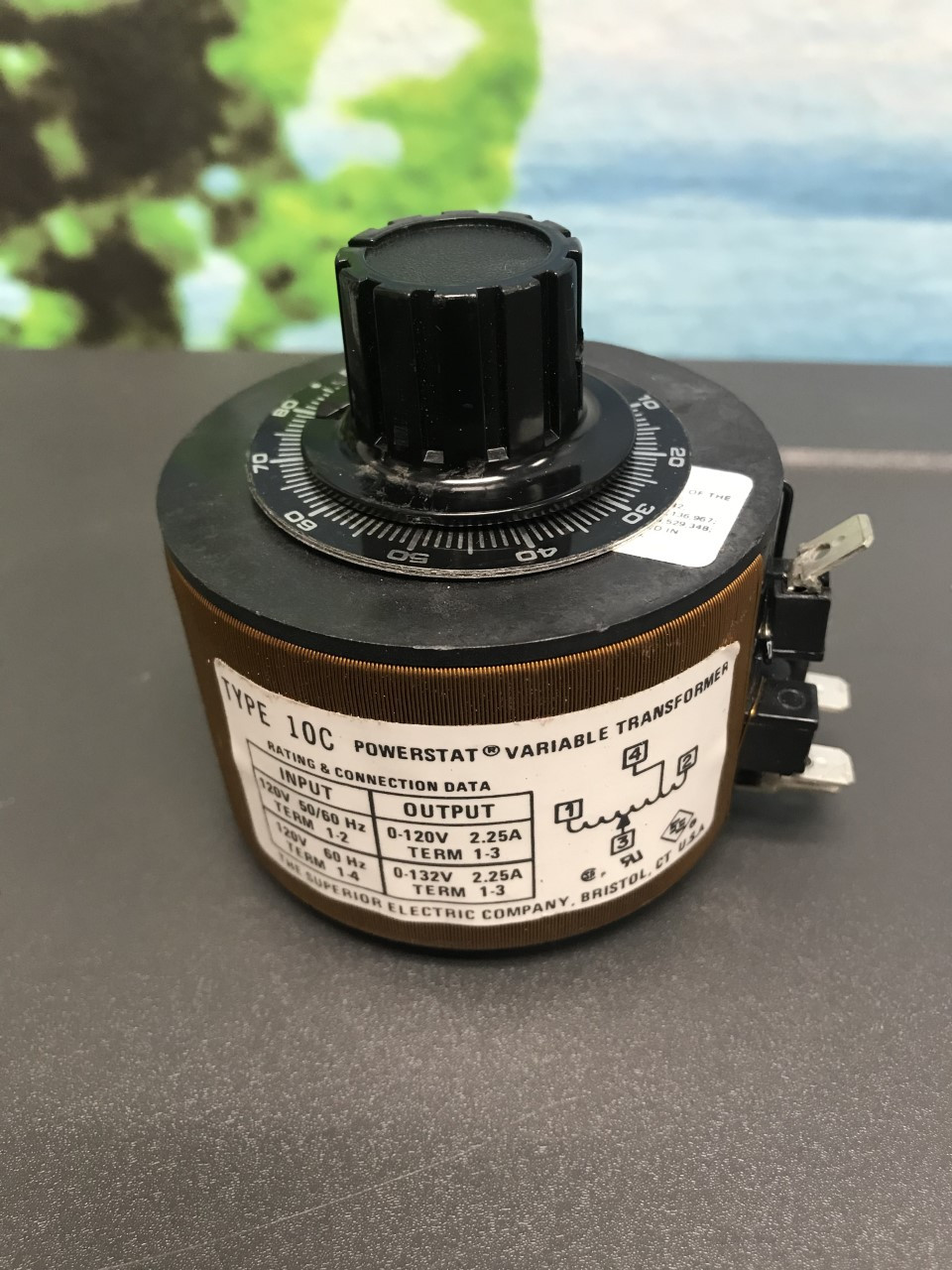
Superior Electric Powerstat 120V 50/60Hz 0-120V 2.25A Variable Transformer 10C
Antique Radio Forums • View topic - Circuit Breakers and Variacs

Autotransformer - The Amazing World of Electronics
Variac question. - Pre-1950 (Antique) - Antique Fan ...
Experimenting with AC and DC voltages – PLCGOODS Automation

Superior Electric 1156D 6.3KVA Variac Powerstat Variable Autotransformer - As Is
Transformers - The Variac
POWERSTAT Variable Transformers | Superior Electric

How to wire a Variac

The “Wrong Way†To Connect A Variac…..and why you might want ...

The Superior Electric, Powerstat 22, 2.25 KVA Variable ...

Shopping for a variac

SUPERIOR ELECTRIC 216CU Variable, Manually Operated, Open, Single Phase, 50Hz / 60Hz, 240V, 280V
Volt-Pac Variable Autotransformer

Powerstat 116 Variable Transformer - YouTube
MZE-Electroarts Entertainment - MZEntertainment.com: Dr. ZEE ...

Am I missing something? Variac content. | Telecaster Guitar Forum
0 Response to "35 powerstat variable autotransformer wiring diagram"
Post a Comment