40 iron carbon equilibrium diagram
If we talk according to the iron-carbon equilibrium diagram the cementite will be converted to the spherical form. Isothermal Annealing. The isothermal process is done for the low carbon steels and alloy for improvement of their machinability. In this process the steel will be heated above the upper critical temperature thus it will convert to austenitic steel pretty much rapidly. …
Properties Endurance Limits of Metals HEAT TREATMENT Iron Carbon Equilibrium Diagram Structural Consituents of Iron-Carbon Alloys Choice of Annealing Treatments T T T Diagram & HardenabiIity Curves. EN 8 & C 4.0 EN 9 & C 55 EN24&40Ni2Cr 1 Mo_28 Salt Mixtures. Composition and Heating Time Annealing & Hot Working Temp. Metals Hardening & …
Nov 18, 2013 · iron carbon equilibrium diagram, ttt diagram and heat treatment ANKIT SAXENA Asst. Prof. @ Dr. Akhilesh Das Gupta Institute of Technology and Management, New Delhi normalising

Iron carbon equilibrium diagram
Classification of materials. Like many other things, materials are classified in groups, so that our brain can handle the complexity. One can classify them based on many criteria, for example crystal structure (arrangement of atoms and bonds between them), or properties, or use.
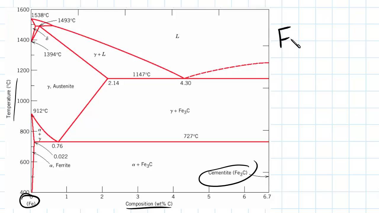
Read More: Introduction to Iron-Carbon Equilibrium Diagram | Structures in Fe-C Diagram. 1. Ferrite: Iron which contains little or no carbon is called ferrite. It is very soft and ductile and is known as alpha iron by the metallurgists. Ferrite is present to some extent in a great range of steels, particularly those low in carbon content, and it is also present, in soft cast iron. Ferrite …
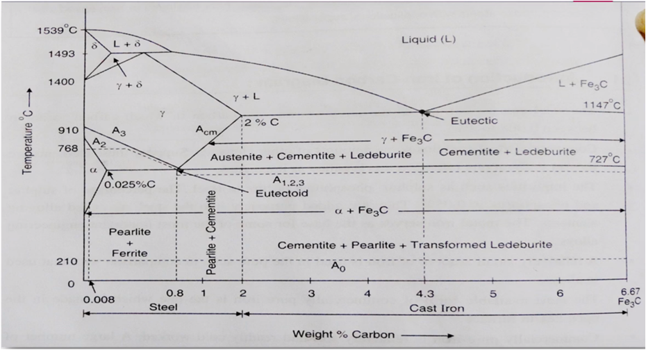
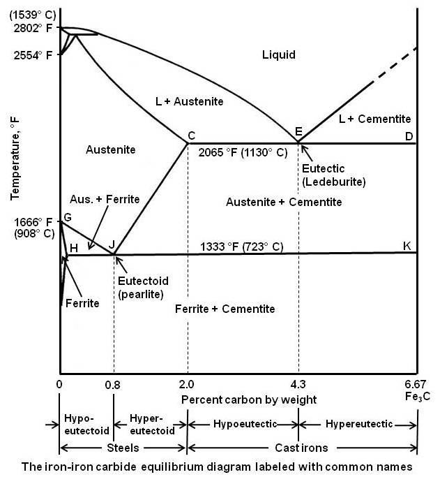
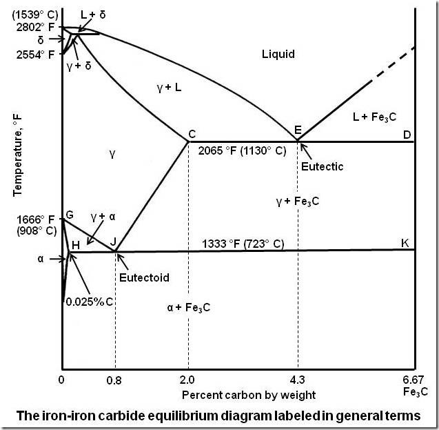
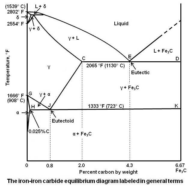
The effects of carbon are best illustrated by an iron-carbon equilibrium diagram. The A-B-C line represents the liquidus points (i.e., the temperatures at which molten iron begins to solidify), and the H-J-E-C line represents the solidus points (at which solidification is completed). The A-B-C line indicates that solidification temperatures ...
Iron carbon equilibrium diagram.
ADVERTISEMENTS: In this article we will discuss about:- 1. Introduction to the Iron-Carbon Equilibrium Diagram 2. Phases in Fe-Fe3C Diagram 3. Critical Temperatures 4.Transformations and Microstructures of Slowly Cooled Steels 5. Methods Used to Distinguish between Free-Ferrite and Free-Cementite 6. Limitations. Contents: Introduction to the Fe-Fe3C Equilibrium Diagram Phases in Fe-Fe3C ...
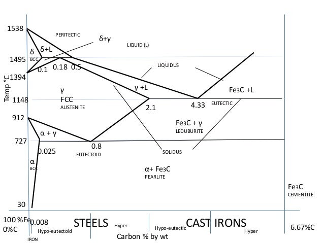
10.03.2020 · The carbon in iron is an interstitial impurity. The alloy may form a face centred cubic (FCC) lattice or a body centred cubic (BCC) lattice. It will form a solid solution with α, γ, and δ phases of iron. Types of Ferrous Alloys on the Phase Diagram
Although, the iron-carbon equilibrium diagram reveals on the phases and corresponding microstructures under equilibrium conditions but several useful properties of the steels can be obtained under non-equilibrium conditions, e.g. variable rates of cooling as produced during quenching and better transformation of austenite into pearlite and martensite. For each steel …
Table of Specification - K-12 - Free download as Powerpoint Presentation (.ppt), PDF File (.pdf), Text File (.txt) or view presentation slides online. tos
Gate metallurgical engineering: iron-iron carbide phase diagram
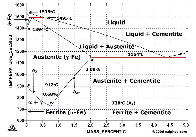
![Iron-carbon phase diagram [SubsTech]](https://www.substech.com/dokuwiki/lib/exe/fetch.php?w=&h=&cache=cache&media=iron-carbon_diagram.png)
Iron-carbon phase diagram [substech]
Iron carbide equilibrium diagram | marine inbox
Coloring vector ironcarbon phase diagram stock vector ...
Iron-carbon phase diagram graphite, png, 1260x1024px, phase ...
Phase diagram iron carbon | metallurgy for dummies
Practical maintenance » blog archive » the iron-iron carbide ...
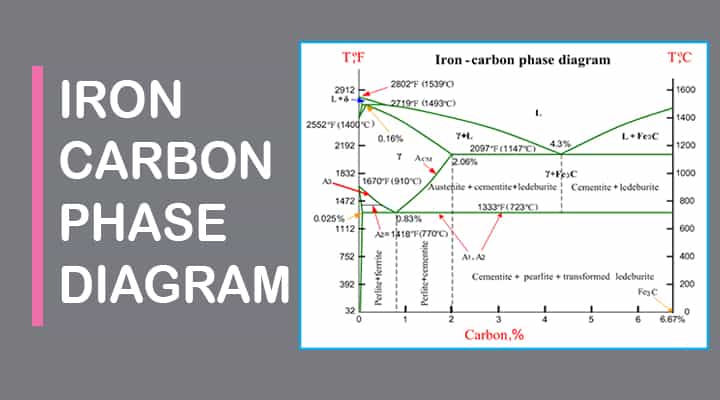
![Iron-Carbon Phase Diagram Explained [with Graphs]](https://fractory.com/wp-content/uploads/2020/03/Phase-diagram-of-steel-and-cast-iron.jpg)
Iron-carbon phase diagram explained [with graphs]

The iron carbon phase diagram... - metallurgical engineering ...

Iron-carbon phase diagram | value creation from uzbekistan
![Iron-Carbon equilibrium diagram [62] | Download Scientific ...](https://www.researchgate.net/profile/Ashwin-Polishetty/publication/268747490/figure/fig11/AS:670010443833358@1536754346351/Iron-Carbon-equilibrium-diagram-62.png)
Iron-carbon equilibrium diagram [62] | download scientific ...

Introduction to iron-carbon equilibrium diagram | structures ...
Introduction to iron carbon phase diagram | engineering materials

Iron-carbon phase diagram |

Iron-carbon phase diagram - edelstahl härten
Iron-carbon phase diagram its defined as:- a map of the ...
Fe-carbon phase diagram - ppt video online download
What is the use of an iron carbide phase diagram? - quora
3 the true equilibrium iron-carbon phase diagram with ...
Iron-iron carbide phase diagram example

Solved by using the iron-carbon (fe-c) phase diagram | chegg.com
Practical maintenance » blog archive » the iron-iron carbide ...

Gate & ese - iron- carbon equilibrium diagram ( in hindi ...
Sketch and explain the iron carbon equilibrium diagram ...

The iron carbon phase diagram

Iron carbon equilibrium diagram ( complete discussion with interview questions)
![Iron Carbon Equilibrium Diagram [PDF|TXT]](https://html.pdfcookie.com/02/2019/12/19/mlxz39d18327/bg2.jpg)
Iron carbon equilibrium diagram [pdf|txt]
Bisakah anda menjelaskan diagram besi karbida besi (diagram ...

Iron carbon phase diagram - google search | metal working ...
Iron carbon equilibrium diagram- how to draw- animation

Mechanical fundas: iron iron carbide equilibrium diagram

Iron –carbon phase diagram
Iron carbon phase or equilibrium diagram or iron carbide ...

The iron-carbon equilibrium diagram :: total materia article
![The iron-carbon phase diagram [46]. | Download Scientific Diagram](https://www.researchgate.net/profile/Muna-Abbass/publication/293333803/figure/fig2/AS:669013386469398@1536516629671/Figure-2-11-The-iron-carbon-phase-diagram-46.png)
The iron-carbon phase diagram [46]. | download scientific diagram

Weiwei (zhuweiwei071010) - profile | pinterest

The iron-carbon alloys and fe-c phase diagram - mechanicalbase
Phase diagrams:

7 iron carbon phase ideas | carbon, iron, mechanical engineering
0 Response to "40 iron carbon equilibrium diagram"
Post a Comment