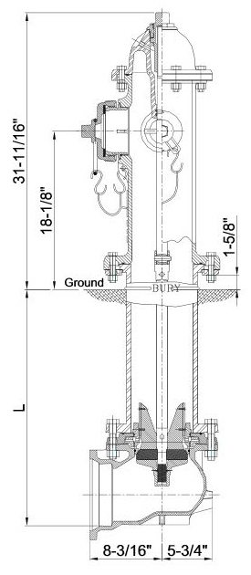
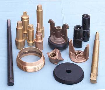
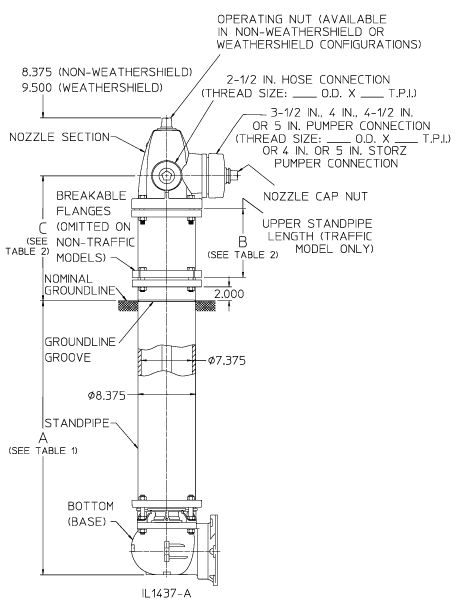
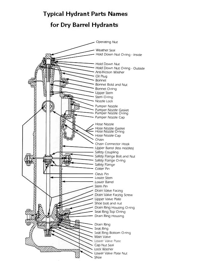
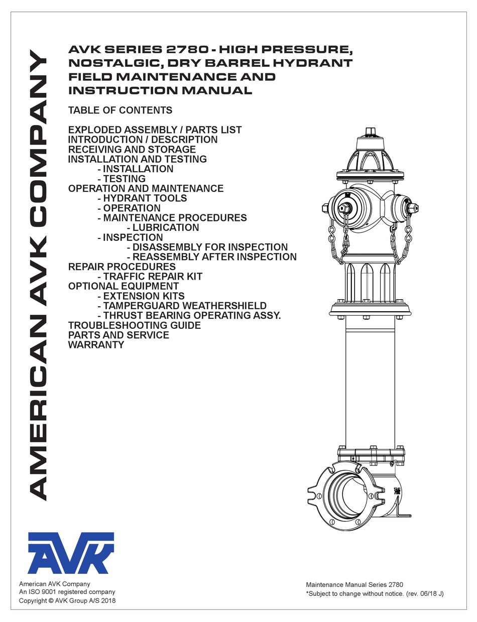
40 fire hydrant parts diagram
Mueller Fire Hydrant History 3 Fire Hydrant History AWWA Dry Barrel Hydrants Year of Manufacture Hydrant Style Model No. Page 2014 - Present Super Centurion® 350 A421 HP & A423 HP 5 1997 - Present Super Centurion® 250 A421 & A423 6 2014 - Present Super Centurion® 250 A454, A455, A458 & A459 6 2014 - Present Super Centurion® 250 Snow Bury (UL Only) A423 7 ...
b-50-b18 fire hydrant parts part numbers with (****) to be specified by customer. *30-51-1 quantity varies with trench depth catalog# part number description qty. 1 **** operating nut 1 2-1 2000001615 bonnet and housing cover o-ring 2 2-2 194572 stem seal o-ring (#214) 2 3 234427 lubricating screw 1
note that the Pacer hydrant can be maintained by just one person. The removal of four nuts and bolts allows access to all working parts. The Pacer hydrant has all the features you expect from a high-quality fire hydrant. The all bronze valve seat and bronze seat insert ensure that the Pacer hydrant remains easy to repair. The Pacer has been
Fire hydrant parts diagram
Parts For Obsolete Hydrants. Trumbull has over 25 YEARS EXPERIENCE in the manufacturing of fire hydrant repair parts. Parts are available for many makes and models. Inquire for minimum quantities and availability of specific parts. AP Smith H200, H205. Mueller Standard & Improved. Kennedy 1080, 1280. Darling Standard & B50B.
Breaking Down Components of a Fire Hydrant. 7/24/2018. Aside from being the historically-preferred location for canine bladder relief, fire hydrants serve an important function in providing access to a water supply system. Types. Fire Hydrants fall within one of two types; wet and dry barrel. Dry Barrel, as implied, is not water-filled until ...
4-1/2 in A421 Super Centurion® 250 Fire Hydrant (1) 4-1/2 in Swivel and Replacement Tail Gasket (1) AKB10003, AKB10001, AKB10004, AKB10002, AKB10005, AKB10007 and AKB10006 Hydrants (1)
Fire hydrant parts diagram.
1 Recreation - The use of fire hydrants for recreation is discouraged by many water utilities. However, in some locations a systematic controlled use of hydrants for recreation is common during the summer months. 2 WateringPoint - When using a fire hydrant for these purposes an approved backflow protection system must be installed.
For the benefit of our customers and potential customers, we have compiled a useful listing of various fire hydrant parts diagrams. All of these files (in pdf format), may also be found from the various manufacterer web sites. Kennedy Model K-81 Mueller Super Centurion. Mueller Modern Model US Pipe Metropolitan M94.
2 FIRE HYDRANT PARTS LIST FIRE HYDRANT METER ITEM DESCRIPTION PART NUMBER QUANTITY 1 16” Seal Wire with Lead Seal 41110-501 1 2 Seal Cap 11098-001 1 3 Calibration Nut 8545-417 1 4 Maincase Bolts 8329-405 10 5 Cover 9639-104 1 6 Drive Spindle Assembly 9485-001 1 7 Calibration Vane Assembly 11097-200 1
4. Flushing Fire Hydrant a. Using a Hydrant Operating Wrench turn the hydrant in the direction of opening indicated by an arrow cast in the hydrant. A pipe wrench is not the equivalent of a hydrant operating wrench. b. Open hydrant at a moderate pace, typically one turn per second. It is not a race.


![Fire Hydrant [1650x2550] drawing with labels and functional ...](https://external-preview.redd.it/_vwX6LftUyX953L-9y4o2_6GTPdc9sWZnjMQH7YopiE.png?auto=webp&s=b557898a0e6fa9b76919e2cbbc24f0970169ca2e)




0 Response to "40 fire hydrant parts diagram"
Post a Comment