39 ford 302 water flow diagram
im looking the complete engine wiring diagram & schematic thats color coded for my 4dr 1994 honda civic sedan has a D15b7 engine in it for now but someone cut up a few wires in diffrent areas. thank you very much its been difficult to find the correct schematic & diagram again thank you #220. Ed Bro (Friday, 29 January 2021 05:49) The D3UZ pump is the standard cast iron water pump used on 289, 302 and 351W engines through 1969. The C5AZ high-flow pump was originally 289 High
Windsor Coolant Flow Diagram. Now you know why it's so important to install the head gaskets with the "FRONT" markings to the front, even though one of them will be installed with the "FRONT" marking upside down. Need to make sure the water/coolant passages are kept open at the rear of the block, to ensure the flow, as shown above, is not ...
Ford 302 water flow diagram
Termodinamica 8 edicion + solucionario, Yunus A. Cengel Did read a blurb on Ford's still new FR-9 NASCAR engine. They mentioned that even as little as a 3-4 degree temperature difference (using the old Windsor design FRPP block and Yates heads) played havoc with hp creation, cylinder to cylinder timing, etc. The new engine was designed with water jackets and overall coolant flow to have zero difference between all eight cylinders. LS Swap Components for 1967-69 Camaro/Firebird: The 1st Gen F-Body is the gold standard for muscle cars. Nothing beats the power of modernizing with a complete LS swap system. From fuel injection, manifolds and fuel pumps all the way to the exhaust system. Holley has engineered these parts to work as a system to deliver the most power and proper fit.
Ford 302 water flow diagram. The water flow on all small block fords is the same. In the water pump through the lower hose. Through the block (with trace amounts going to the head through the holes through the head gasket. At the back of the block the water flows through 2 big holes up into the head Then the water flows forward through the heads. Water Pump, Mechanical, High-Volume, Aluminum, 1986-1993, Ford, 302/351W, Driver Side Inlet, Reverse Rotation, Each. Part Number: MIL-16233 Water flow direction in radiator. Replaced water pump on 2010 f-150 4.6 3V engine. Pump has no. connection for radiator hose. Upper hose connects to thermostat housing, and lower hose connects to block at bottom of engine on drivers side. So, I have a 302 ford motor that I installed in my 1953 ford f100 pickup. I rebuild the motor and had problems at first with the water pump . When I rebuilt the motor the timing cover was bad I got one from a friend and installed it with a new water pump (Note Need the style that takes a mechanical fuel pump) after installing I had problems with ...
The Ford engineers supplied a larger mass air flow meter which was the same size as the '93 Cobra. Pushrod discontinuation With Ford making the switch to the 4.6-liter modular engines in 1996 for the Mustang, they did produce the 302 up until 2001 which was an engine option in the Ford Explorer and standard in the Mercury Mountaineer. Aftermarket high-flow cast-iron water pumps look basically the same as original equipment without the Ford casting number. This is an aftermarket 351C/351M/400 water pump. It illustrates what happened in 1970 on all Ford small-block V-8s: Ford went to a true crossflow cooling system, which meant moving the water pump inlet to the driver's ... Factory Ford shop manuals are available from Helm Publications, 1-800-782-4356 5) Coolant Flow Diagram: If a heater circuit is not used then the heater supply must be connected to the heater return to allow air to be purged from the right hand cylinder head and provide sufficient coolant flow through the right hand cylinder head. Ford 302 water flow diagram. Alternator voltage regulator instrument panel starter and drive distributor. Boss 302s for 1969 were fitted with a 1969 specific high flow water pump c9zz 8501 a. Ford started a crash development program to fix the problem at ford engine and development during 1967. A year later in 1970 the boss 302 engine was fitted with the d0zz 8501 b water pump. Ford truck ...
Oct 24, 2019 · This is a post titled ford c4 transmission parts diagram we will share many pictures for you that relate to ford c4 transmission parts diagram. Oct 04, 2021 · In the current C4 transmission, a newly designed line coasting boost valve will automatically raise control pressure for manual 3-1, 3-2, and 2 -1 shifts at closed throttle at all road speeds. EZ Read simple diagram of the Big Block Chevy Cylinder Head Torque Sequence. ... the bolt holes drilled through to the water jacket. Use a good sealer on the threads (ARP, Permatex) something . ... Ford 260-289-302 Firing Order; Ford 351C 351M 400M Firing Order; Ford FE Firing Order; 1965-1972 (6 Cyl. 240, 300 and 8 Cyl. 302, 352, 360, 390 engines) - F100/350 1406 x 1024, 383K Valve Assy. - (Exhaust Thermostat Control with Arm Type Counter Weight - Typical Jul 23, 2004. #2. Originates (pushes) at the water pump, flows through the heater core, back to the intake manifold. Note: at the manifold the heater inlet sits next to the engine outlet. Movement of water through the manifold and into the radiator causes a small vaccuum at the heater return line (it sucks)!
.-GPSA Engineering Data Book [Gas Processing] 12th ed
FORD Car Fault Codes DTC - Focus, Fusion, Mondeo, Transit, Kuga, EcoSport, C-Max, Fiesta, Maverick, Galaxie, Explorer, Escape, Ranger.. FORD Common Faults P0000 Code P0000 means that no errors were detected in the memory of the control unit P1000 EOBD system not tested before use. The P1000 code does not indicate a malfunction, but indicates a self-tuning EOBD.
Engines cooling systems acting odd, somewhat like a blown head gasket, yeat no water/steam seen in exhaust, and none in oil. Im wondering the direction of water flow. By looking at the pump and the fan direction, Im thinking the water goes IN at the intake and pumps out from the waterpump, pushing the water UP through the radiator.
This is the Head Bolt Torque Sequence (Pattern) for Ford's small block. This includes 260, 289, 302, Boss 302,
That diagram which shows Ford PN's for the block off is interesting. Where could I get those if I decide to go that route. I don't have access to dies and taps to get a brass plug in there and unfortuneately, the waterpump is on my car with a new radiator, etc.. as I did this last night only to find I had an open outlet with no where to go ...
Here are two examples of small-block Ford water pumps. On the left is a right-hand inlet water pump for the 221/260/289/302 prior to 1970. On the right is the smaller reverserotation water pump for 1994+ 5.0L High Output, which also calls for the appropriate timing cover. Ford Racing Performance Parts offers the enthusiast two types of water pumps for small-block Fords: shorty, and regular ...
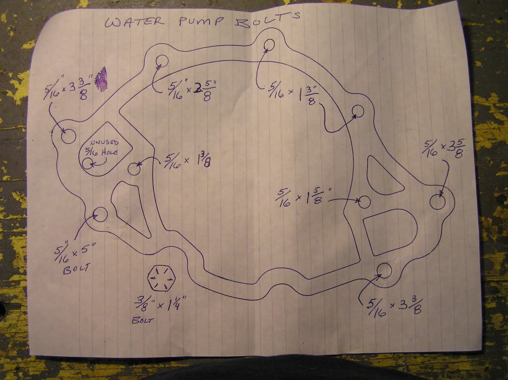
For example, the LTD series had 2 to 3 different pumps for the 5.8L small blocks for any given year depending on exact model. Same deal with pickups. Hit the 'yards. To tell a standard or reverse timing cover or pump, note in the pic below there are 9 mounting bolts on standard-rotation, and 7 mounting bolts on reverse rotation.
4 Jul 2010 — 1948 - 1956 F1, F100 & Larger F-Series Trucks - Which Way Does The Water Flow - This undoubtedly is a dumb question question but, which way ...
When using a front sump oil pan you can use Ford part# M-6059-D351 (STD rotation water pump) or M-8501-B50 (reverse rotation) water pump front cover with provision for a dipstick. The dipstick needs to be in the oil pan with a rear sump application. The DART blocks do not have a provision for a dipstick.
30.11.2021 · Ford 2v motorcraft 2100 2150 2 Ford Carb Identification: Ford Motorcraft Autolite 740 1100 2100 2150 4100 4300 4350: Full Size View 1100 1101 1250 Parts Page Diagram: Full Size View 2100 2150 Parts Page 2100 Diagram 2100 Late Diagram 2150 Diagram: Full Size View 740 Parts Page Diagram: Full Size View AUTOLITE 2100 CARBURETOR KIT FORD MUSTANG 289-302-351-390 …
Belt Paths Refer to the belt path diagram under the hood, typically located on the fan shroud or front fender brace, or locate the water pump pulleys on the vehicle. Compare the diagrams below. Water pump pulleys running on the inside surface of the belt indicate a Standard Rotation water pump (grooved side of belt). W
Coolant Flow Radiator And Engine Block Below is an explanation of this system's operation The Thermostat Just like your body needs to warm up when you begin to exercise, your car's engine needs to warm up when it starts its exercise. The thermostat provides control for your engine's warm-up period. The thermostat is located between the engine and the radiator. This little temperature-sensitive ...
getting the correct pulley set up for a SBF can be trickyFOMOCO this will help sort it out
Does anybody have or know where there is a diagram of how the 302 H.O. motor cooling system works? If I remember correctly the flow is from the top hose down through the system and back around, or is it the other way? Judging by the way the thermostat looks, I'd say antifreeze flows past it into the motor and down around. So, if I don't have any antifreeze in my block and fill my radiator, how ...
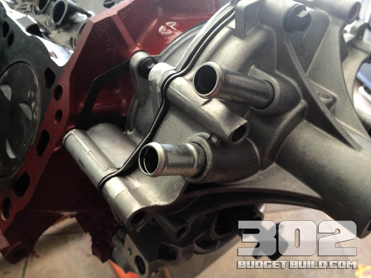
Stock water pumps may be modified to improve flow. By removing the rear cover (FE) or separator plate on the (small blocks) a round flat metal disc pop riveted to the back of the impeller will move more coolant at low speed and reduce high rpm cavitation. ... Ford water pumps have the lower radiator hose casting, two exit ports into the block ...
4,415 Posts. #5 · Mar 11, 2020. Only show this user. The newly install parts on Dans68 is exactly correct for 65-69 on all 289/302/351W engines. The illustration is for the 70 and newer 302/351 engines. Ford changed the setup when the lower radiator hose was switch from passeners side 60's, to drivers side in 70.
Watch Sam Mahdavi install a Tuff Stuff high flow water pump on a Ford small block engine.
Ford F150 Heater Hose Diagram. ford 4 6 5 4 6 8 heater hose under intake replacement ford 4 6 5 4 6 8 heater hose under intake replacement the easy way 1999 ford expedition 5 4 heater hose 99 ford f150 heater 1997 ford f150 4 6 heater hose diagram imageresizertool 1997 ford f150 4 6 heater hose diagram moreover 6e944 2004 ford explorer 4 0 one vac line along with 2d4cs 2004 ford explorer 4 0l ...
Ford 302 Water Flow Diagram. Flow Of Raw Water Through Motor - CorrectCraftFan.com Forums - Page 1. Closed loop. Heater Hoses - Gary's Garagemahal (the Bullnose Bible) Heater hose routing orig . DIAGRAM Mustang 302 Engine Diagram FULL Version HD Quality Engine Diagram - MILSDIAGRAM.RADIOTELEGRAFIA.IT. Engine 302 01. Cobra Club Forums. JSnXqlb. Ford Truck Technical Drawings And Schematics ...
I'm running a new 3 core radiator, a new high flow water pump, and a new t-stat (oem 190), all new engine gaskets torqued to specs, no heater core, mech. Photo of a throttle body, throttle body position (TPS) sensor is the black part to the lower right: The computer monitors the correlation of both voltages. chevy spends millions researching and developing there **** im pretty sure they know ...
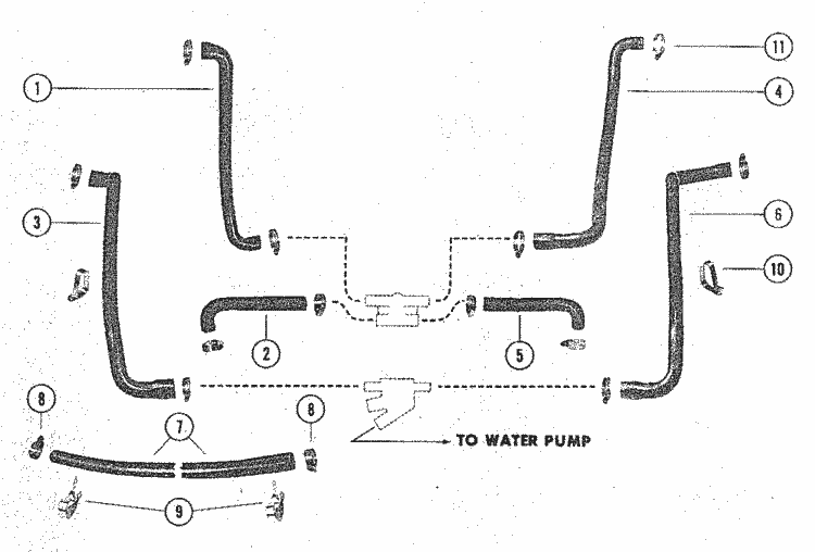
As shown in the diagram below, raw water is picked up through the drive pickup or through a hull mounted pickup, if present it will pass through a sea strainer to clean debris out of the water. From there it will pass through the raw water pump. ... 302/351 Engine Ford 190-240 AQ Ford, Half-System Volvo Closed Cooling System - 305/307/350 ...
Ford Truck Diagrams and Schematics. Alternator Voltage Regulator Instrument Panel Starter and Drive Distributor
Find FORD 5.0L/302 Fittings & Hoses and get Free Shipping on Orders Over $99 at Summit Racing!
Hi, Does anyone have a diagram showing the flow of coolant around the engine / radiator etc. I have a 302 engine and the two small outlets on the water pump have been bridged - I assume these were for the heater matrix, and at the back of the heads there seems to be coolant ways which have been blocked off, I'm worried that this will over heat the heads if there is no flow!
6,540 Posts. #2 · Jan 16, 2002. Jesmol, I think the XG has the same engine/gear as the EBII/ED sedan. If so that from memory the therostat housing is different, not sure if thats going to effect flow direction. Just out of interest what part number thermostat did you use. I got Ford part no. ART-92-G for my dads EL and it specified a flow ...
LS Swap Components for 1967-69 Camaro/Firebird: The 1st Gen F-Body is the gold standard for muscle cars. Nothing beats the power of modernizing with a complete LS swap system. From fuel injection, manifolds and fuel pumps all the way to the exhaust system. Holley has engineered these parts to work as a system to deliver the most power and proper fit.
Did read a blurb on Ford's still new FR-9 NASCAR engine. They mentioned that even as little as a 3-4 degree temperature difference (using the old Windsor design FRPP block and Yates heads) played havoc with hp creation, cylinder to cylinder timing, etc. The new engine was designed with water jackets and overall coolant flow to have zero difference between all eight cylinders.
Termodinamica 8 edicion + solucionario, Yunus A. Cengel


0 Response to "39 ford 302 water flow diagram"
Post a Comment