39 0-10 volt dimming wiring diagram
Nov 16, 2020 - 0-10 Volt Dimming Wiring Diagram . 0-10 Volt Dimming Wiring Diagram . Perfect 1 10v Dimming Wiring Diagram Image Collection Electrical. 0 10 Volt Dimming Wiring Diagram Best Lighting Dmx Dimmer System. 0 10 Volt Dimming Wiring Diagram Inspirational Wiring Diagram Light
0 10 Volt Dimming Wiring Diagram- wiring diagram is a simplified okay pictorial representation of an electrical circuit.It shows the components of the circuit as simplified shapes, and the faculty and signal contacts between the devices.
Wiring Diagram 1 Insulating Label Green Ground Black White Red Hot (Black) Neutral (white) Line 120/277VAC 60Hz Dimmer) Gray (-) Yellow To Lamps Red Blue 0-10 VDC Ballast Yellow/ Red 1 3 7 Matching Remote Additional Neutral Wire 2 Dimmer 2 3 4 Red Violet White Yellow/Red Gray Black Green 6 5 1 Wiring Diagram 2 Green Ground Green Ground White ...
0-10 volt dimming wiring diagram
Lutron 0 10V Dimming Wiring Diagram - Wiring Solutions - 0 10 Volt Dimming Wiring Diagram Wiring diagram also gives beneficial suggestions for tasks that might demand some additional equipment. This e-book even includes recommendations for added materials that you might want in order to end your assignments.
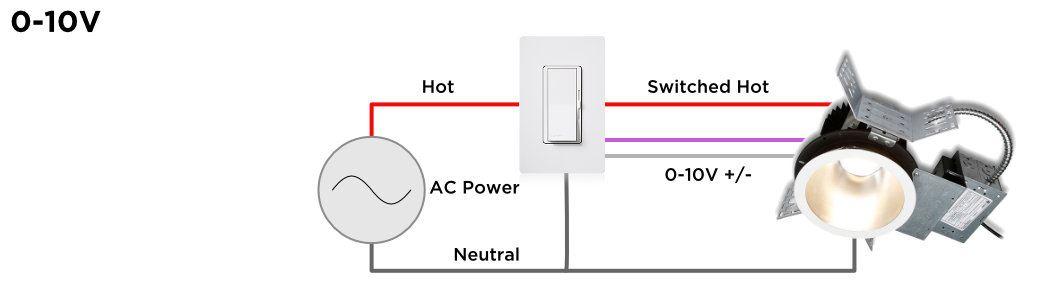
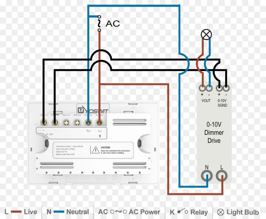
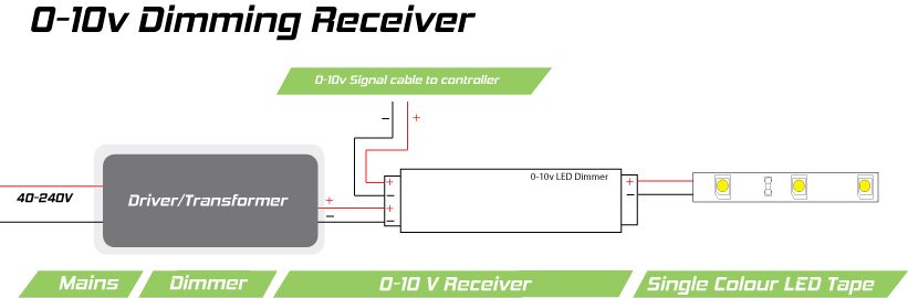
A: Zero to ten volt (stylized as 0-10v) is actually one of the earliest signaling system invented for lighting control and is also one of the simplest: it uses a control signal of low voltage that ranges from 0 to up to a maximum 10 volts. The amount of volts sent to the LED driver, tells it how bright to be. Send 0 volts and the light is off. Send 10 volts and the light will go to maximum power.
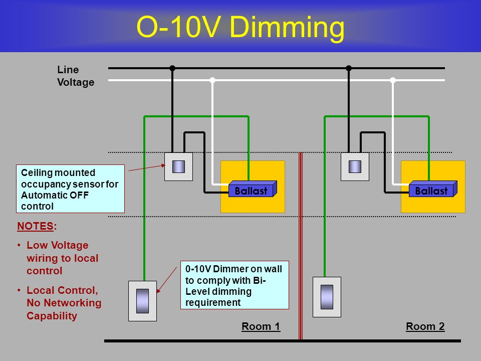
0-10 V Ballast/Driver Dimming With ON/OFF Control Wiring Diagram Using Relay Figure C1: Dimming With ON/OFF Control Via Relay Connect the control as shown in Figure C2. Do not install the Relay in the same wallbox as the low-voltage control. Refer to the wiring sheet included with the Relay for more information. 0-10 V Ballast/Driver White ...
0-10 volt dimming wiring diagram.
0 10v Dimming Ballast Wiring Diagram. 20 Amp 250 Volt Plug Wiring Diagram. 30 Amp 250 Volt Plug Wiring Diagram. 48 Volt Ezgo Txt Wiring Diagram. 220 Volt Air Compressor Wiring Diagram. 240 Volt 50 Amp Plug Wiring Diagram. Club Car Wiring Diagram 36 Volt. Club Car Wiring Diagram 48 Volt.
Description: Low Voltage Led 0-10V Dimming | Usai pertaining to 1 10V Dimming Wiring Diagram, image size 940 X 724 px, and to view image details please click the image.. Honestly, we have been realized that 1 10v dimming wiring diagram is being one of the most popular issue at this moment. So that we attempted to obtain some great 1 10v dimming wiring diagram image for you.
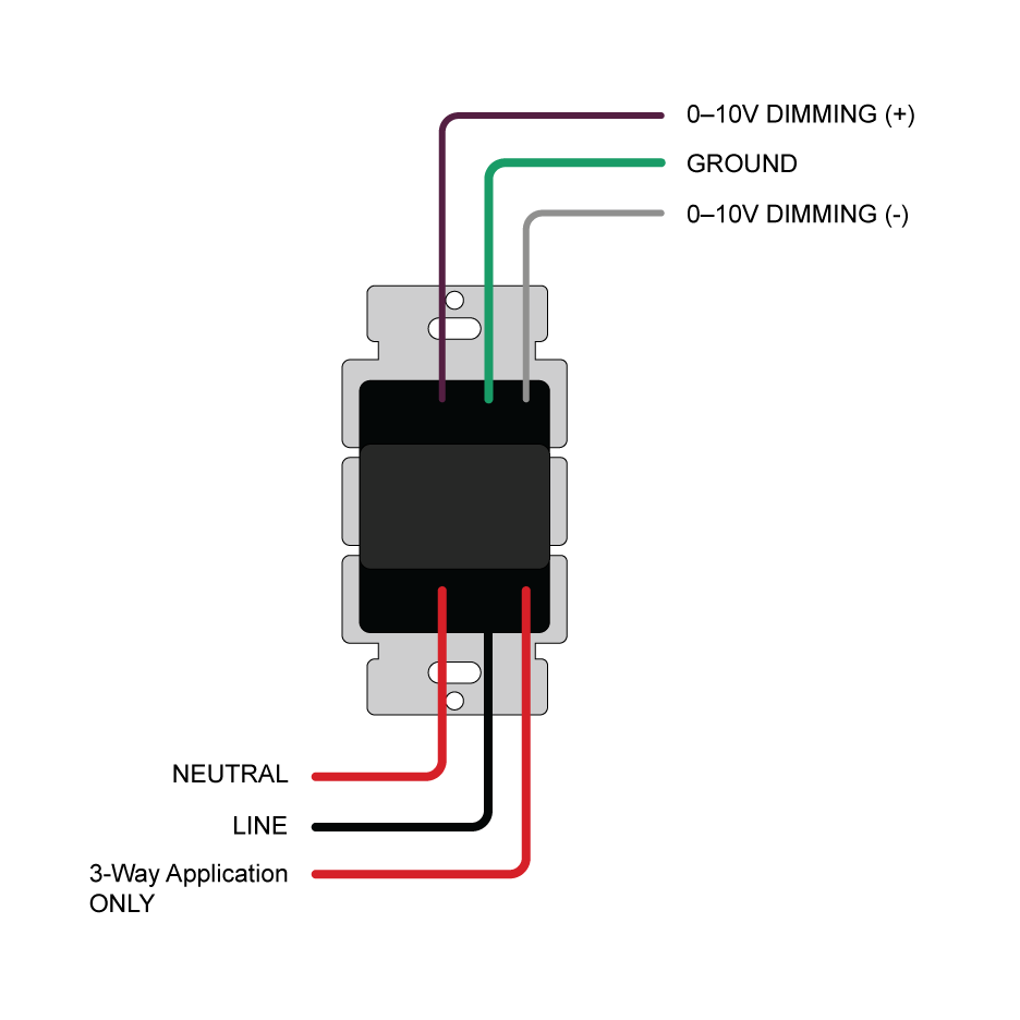
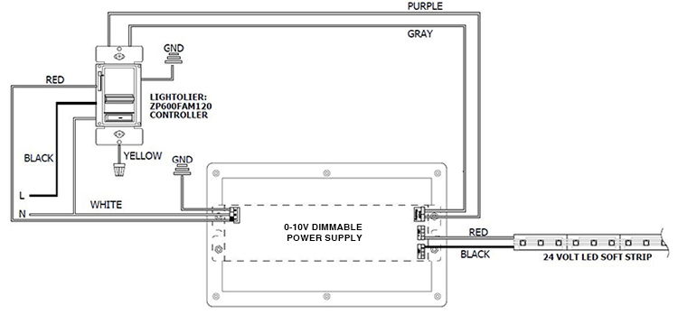
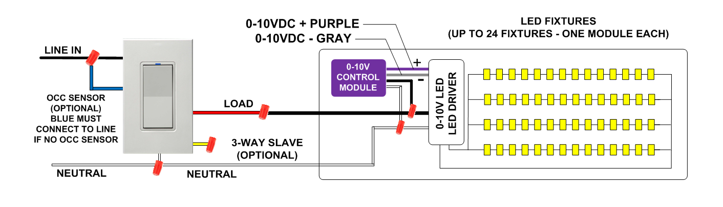
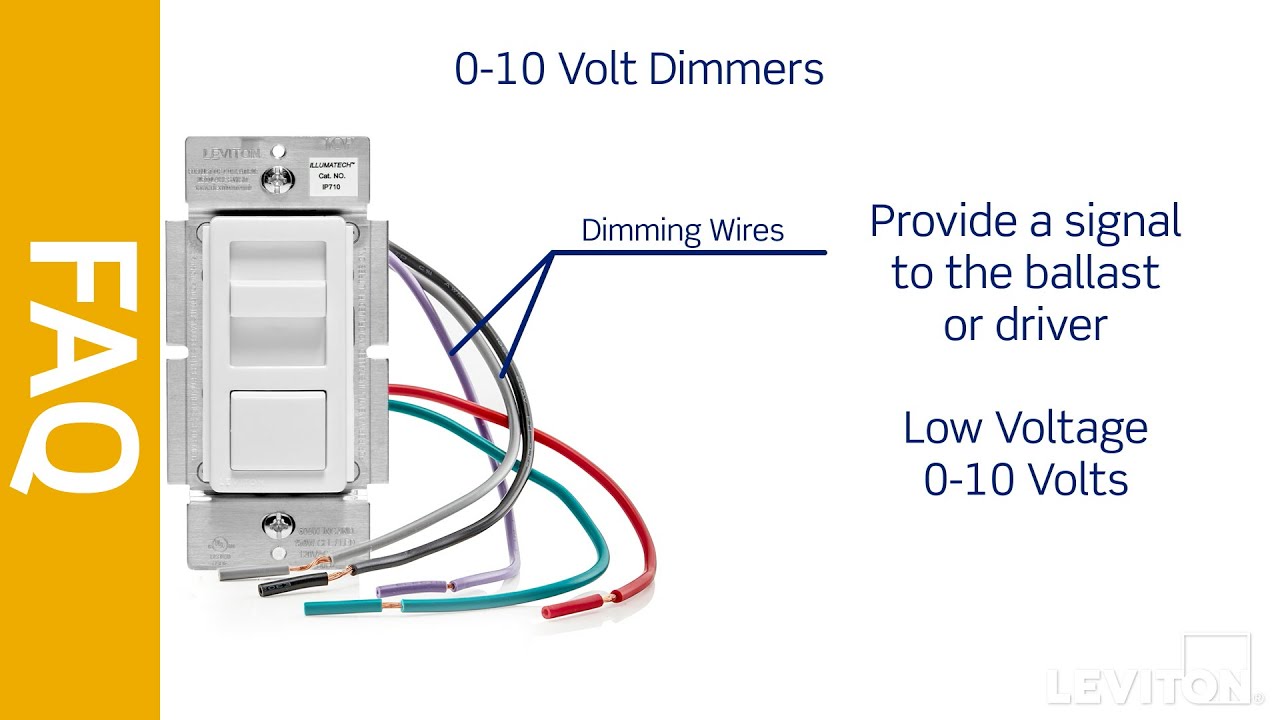
The dimming signal is usually connected to the lighting driver with a purple wire, which carries the 10 volt charge, and a grey wire, which is the common wire carrying the signal. These connect the dimming controller to one or more LED drivers that have the correct input for 0 - 10 V dimming.
At 0 Volts the device will dim to the minimum light level allowed by the dimming driver, and at 10 Volts the device will be operating at 100%. A 0-10V dimmer is considered analog dimming, and all USAI 0-10V dimming options are considered to be "sink" type dimming. A typical 0-10V wiring diagram is shown below: 0-10V Dimming
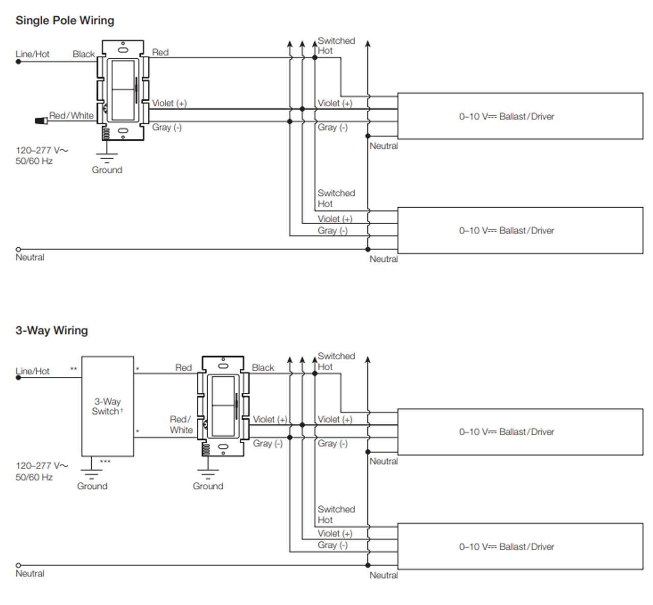
SKYE Series - 0-10V Dimmer Wallstation Overview The SKYE 0-10 Volt Dimmer provides full-range classic linear-slide dimming for 0-10V compatible dimmable light sources. These units are ideal for light commercial applications and are compatible with decorator style devices and wallplates. The preset "ON/OFF" switch
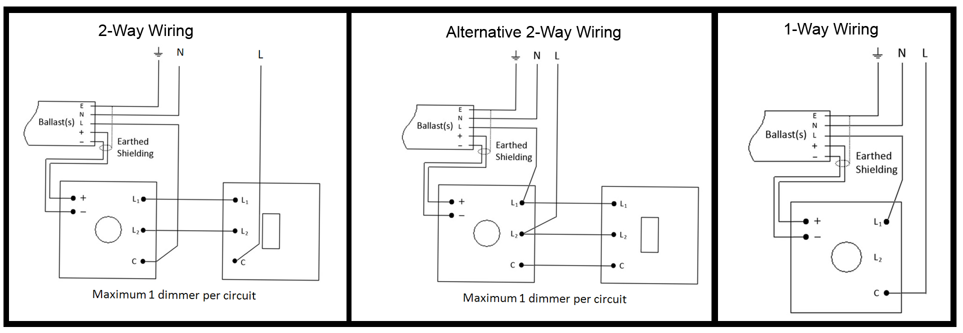
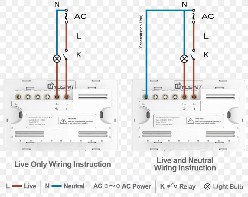
0-10V 3 Way Dimmer Switch Wiring Diagram Source: www.literitecontrols.com. 0-10V 3 Way Dimmer Switch Wiring Diagram Source: i.stack.imgur.com. Read cabling diagrams from negative to positive plus redraw the circuit like a straight range. All circuits are usually the same ~ voltage, ground, solitary component, and switches.
Lutron 0 10V Dimming Wiring Diagram - Wiring Solutions - 0 10 Volt Dimming Wiring Diagram Wiring diagram also gives beneficial suggestions for tasks that might demand some additional equipment. This e-book even includes recommendations for added materials that you might want in order to end your assignments.
(one cable is a 3 wire)Ground Hot Neutral 100-277v power (the other cable is a 2 wire) for dimming Purple Represents + 10 volts and a gray wire representing the signal. I don't have any paper work on these fixtures but they are the newer style fixtures that utilize 1 to 10 volts for dimming as apposed to 0 to 10 v
There is no signal per se- the 0-10 volt determines what level to dim. You can run separate low voltage wire or if you want to get really fancy, they sell MC Luminary cable that has your line voltage and low voltage wires inside. 1
You probably already know that maestro 0 10v dimming wiring diagram has become the top issues on-line right now. Depending on the information we had from adwords, maestro 0 10v dimming wiring diagram has very much search in google web engine. Diva Preset V dimmer provides dimming control of LED drivers, fluorescent ballasts and HID ballasts.
0-10V dimming wiring diagram 0-10V dimmer switch Leviton IP710-LFZ or equal For other types of dimming control systems, consult controls manufacturer for wiring instructions switched hot (black) switched hot (red typical) low voltage dimming wires (purple & gray typical) + Electrical Panel hot (black typical) 120V or 277V, 60 Hz
Used as an early fluorescent dimming system and still used today, 0-10V dimming has been adapted to become a reliable LED dimming control protocol. 0-10 V is one of the earliest and simplest electronic lighting control signaling systems; simply put, the control signal is a DC voltage that varies between zero and ten volts.
Varilight specialist modules
A typical V wiring diagram is shown below: V Dimming. DIML2: Our standard V dimming driver option is often provided standard (check spec sheets) and dims down to 10% at minimum light level. 0 10v Dimmer Switch Wiring Diagram - A schematic shows contacts in a circuit in a pretentiousness that is positive and standardized.
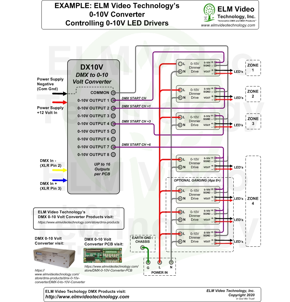
Dmx 0-10 volt analog converter pcb
Find your 0 10 volt dimming wiring diagram here for 0 10 volt dimming wiring diagram and you can print out. Search for 0 10 volt dimming wiring diagram here and subscribe to this site 0 10 volt dimming wiring diagram read more!

0 10 volt dimming wiring diagram | diagram, wire, emergency power
Dimming Diva 0 -10 V dimmer page 4 Nova T* 0 -10 V dimmer page 6 Dimming and sensing Maestro 0 -10 V dimmer sensor page 8 Dimming, sensing, personal control, and daylight harvesting Individual fixture dimming, sensing, personal control, and daylight harvesting PowPak dimming module wh ti 0 -10 V conort l page 10
Bincolor tinggi tegangan 0-10v sinyal analog lampu led dimmer ...
0-10v dimming is a lighting control method that—on direct current voltage (DC) between 0 and 10 volts—can produce varying light intensity levels. This simple lighting control system connects to your LED fixtures to provide multipurpose lighting solutions and ambiance.
Dim14 - led dimmer, 0-10 volt controlled, pwm, 12v 24v low ...
0-10 volt dimming wiring diagram - You will want a comprehensive, expert, and easy to understand Wiring Diagram. With this kind of an illustrative guidebook, you are going to be capable of troubleshoot, stop, and complete your projects with ease.

Led control dimmer 0 -10v 1-10v led light dimmer switch ac110v 220v brightness easy adjustable recessed installation
5.7.2020 · Polaris Ranger Wiring Diagram. Collection of polaris ranger wiring diagram. A wiring diagram is a streamlined standard photographic representation of an electric circuit. It shows the parts of the circuit as simplified shapes, as well as the power and also signal connections between the gadgets. A wiring diagram typically gives info regarding the loved…

Eforlighting 0-10v 1-10v led light dimmer switch ac110v 220v led controller potentiometer for led lamp
Lutron 0 10v Dimmer Wiring Diagram Lutron Diva DVSTV V Dimmer for fluorescent and LED The Lutron Diva DVSTV is a v dimmer that easily Lutron DVSTV v Installation Instructions. 0-10 V is quickly becoming one of the more popular dimming technologies with wired occupancy sensors, for V . Horizontal Beam Diagram. 5 ft. ( m ).
Dimmer buyer's guide: dimming technologies
0 10v 3 Way Dimmer Wiring Diagram. Line voltage switch with dimming sensorworx low led 0 10v usai ds710 10z switches dimmers lutron diva dimmer for fluorescent fixtures single pole or 3 way white dvstv 453ph wh the how to setup dimmable high bay parking lot lights 10volt 10 volt explained etl listed 110 277v china controller made in com leviton ...
Dimmer
According to earlier, the traces at a 0 10 Volt Dimming Wiring Diagram signifies wires. Occasionally, the cables will cross. However, it doesn't mean link between the wires. Injunction of 2 wires is generally indicated by black dot in the intersection of two lines.
0-10 v lighting control dimmer wiring diagram light switch ...
0-10 Volt Dimmer Switch Wiring Diagram from cdn.shopify.com Print the wiring diagram off plus use highlighters to trace the signal. When you make use of your finger or perhaps the actual circuit with your eyes, it is easy to mistrace the circuit. 1 trick that We 2 to printing a similar wiring plan off twice.

0-10 volt or 1-10 volt dimming | electrician talk
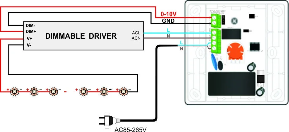
led driver white black hot/line common/neutral 0-10v dimmer gray (-) purple (+) 0-10v dimming diagram 120v line voltage led load low voltage dc wiring diagram powered by ltf ® l.t.f, l.l.c. phone: (847) 498-5832 fax: (773) 337-5628 email: sales@ltftechnology.com
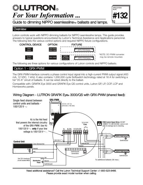
For your information - lutron
Can 100% dimming actually be achieved with 0-10V dimming? Any time I have installed it, including residential, the lowest dimming setting on the dimmer is still quite bright. Dim but still enough light to wonder why it's called 0-10V. I always use Lutron DVSTV dimmers though, haven't tried the pass and seymour RH4BL3PTC listed in the OP.
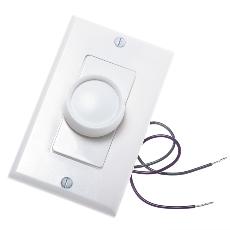
0-10 volt dc low voltage dimmer with rotary dimmer switch
Dvstv-wh lutron diva 0-10v dimmer switch white with wallplate
0-10v led switch and slide led dimmer - single pole/3-way ...

Zaniboni lighting : wiring diagrams part 1 : led lighting

Leviton led 0-10vdc low-voltage slide dimmer switch
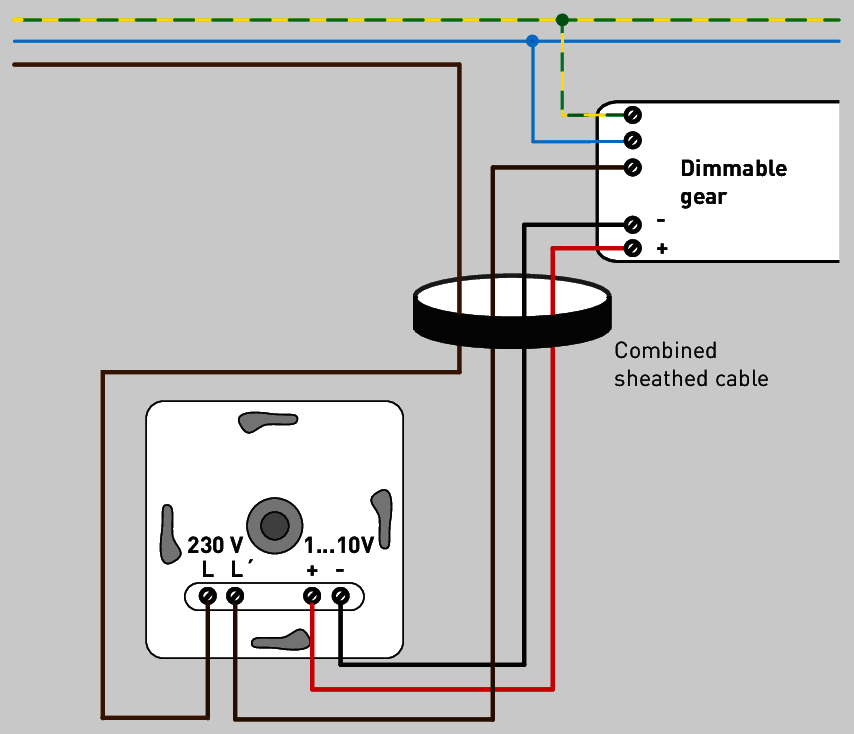
1…10 v interface
Residential dimming guide
0/1-10v dimmable led tri-proof lighting pc housing 600mm 30w ...

Line voltage switch with dimming - sensorworx

0-10v dimming basics and troubleshooting | moons' spark

Pdf) volt dimming wiring diagrams | iroel dot org - academia.edu
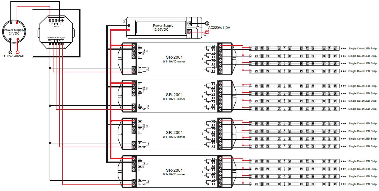
Rotary 0-10v led dimmer switch sr-2202-1-10v
Lightology | what is 0-10v dimming?
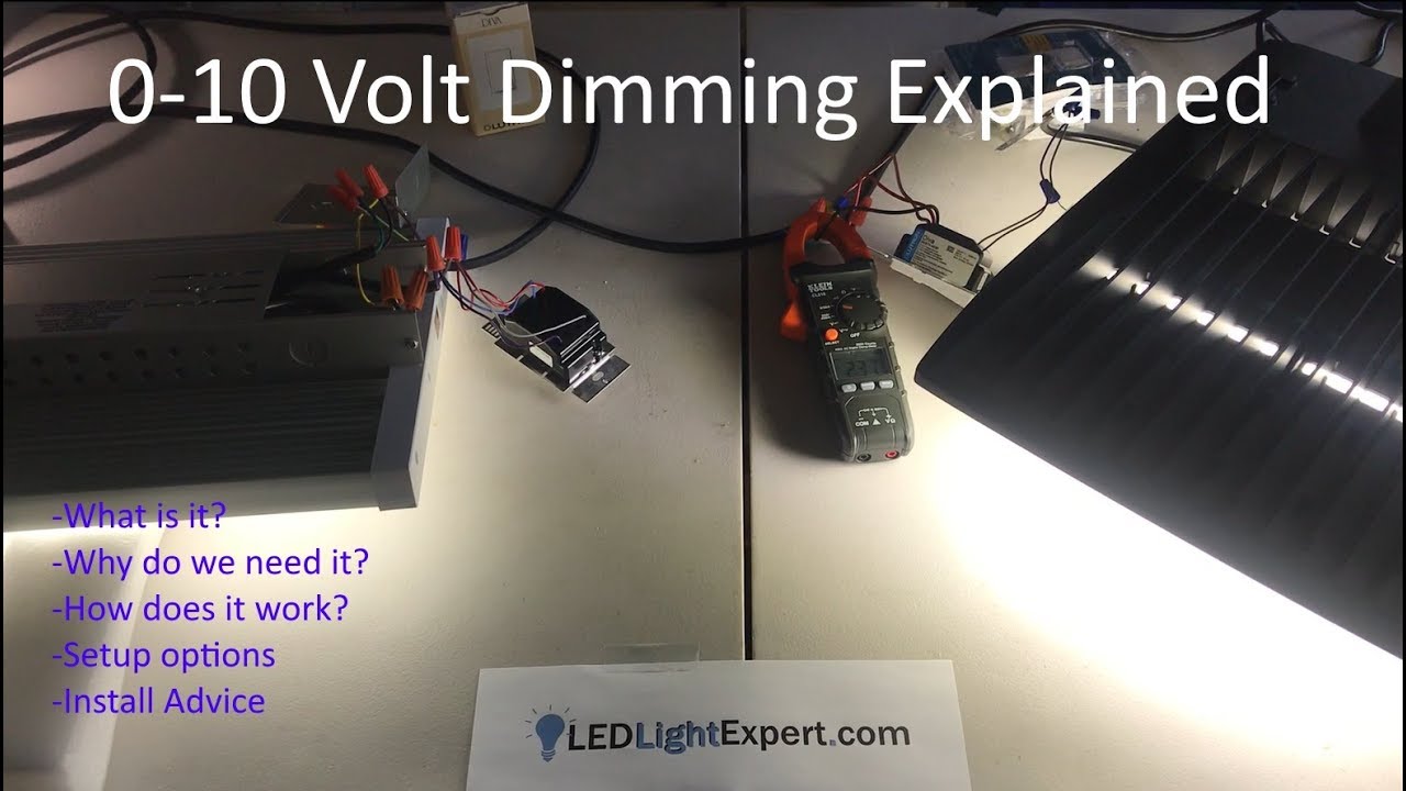
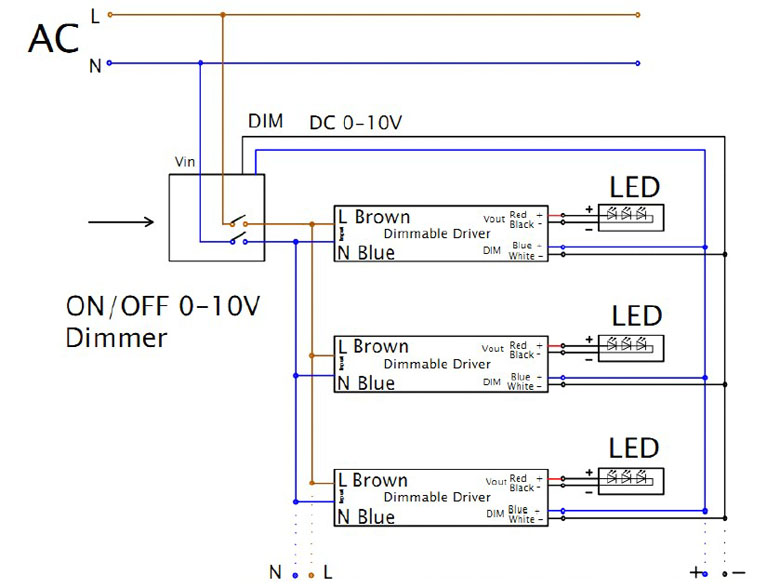
0-10v dimming explained - what is 0-10 volt dimming? how does it work? installation of 0-10v
010 v kontrol pencahayaan, dimmer, pencahayaan gambar png
Led office dimming solution (0-10v fixtures) - no addition ...
Brian liebel, pe, lc afterimage + s p a c e - ppt download
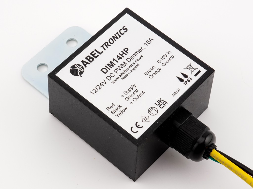
Dim14hp - led dimmer, 0-10 volt controlled, waterproof, pwm ...
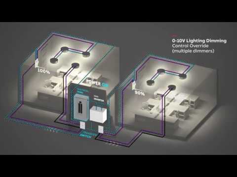
Abb mini inverter wiring diagram-multiple 0-10v dimming control

How to setup dimmable led high bay or led parking lot lights ...

Ip710-lfz

Zaniboni lighting : wiring diagrams part 2 : led lighting

Dimming (0-10v) - sensorworx
All about 0-10v control for leds - instyle led
Leviton answer series: 0-10v dimmers

Zaniboni lighting : wiring diagrams part 1 : led lighting
0 Response to "39 0-10 volt dimming wiring diagram"
Post a Comment