38 honeywell s8600 wiring diagram
All wiring must Wiring Diagram Thermostat Honeywell VisionPRO TH Series Installation Manual .The Honeywell VisionPro with built in wi-fi is a touch screen thermostat which allows remote access through a smart phone, tablet or computer. It controls up to 3 Heat/2 Cool heat pump systems or up to 2 Heat/2 Cool conventional systems.
Honeywell S8600 Wiring. Jump to Latest Follow 1 - 20 of 35 Posts. 1; 2; Next. 1 of 2 Go to page. Go. B. bdp1999 · Registered. Joined May 2, 2012 · 26 Posts . Discussion Starter · #1 · May 2, 2012. Only show this user ...
NetAXS™ NX4L1 Access Control Unit Installation Guide, Document 7-901099V3 11 NetAXS™ NX4L1 Installation Guide 1.0 Notices 1.1 Warnings and Cautions WARNING Fire Safety and Liability Notice: Never connect card readers to any critical entry, exit door, barrier, elevator or gate without providing an alternative exit in
Honeywell s8600 wiring diagram
Nitro Nx 882 Wiring Diagram; Headlight Wiring Diagram For 2016 Vip 50 Cc Scooter; Honeywell S8600 Wiring Diagram; Beneteau 331 Wiring Diagram With Volvo Engine; Fishman Fluence Modern 7 Wiring Diagram; Aahd2-hy Motherboard Wiring Diagram; 2000 Vw Beetle 1.8t Battery Top Fuse Box Wiring Diagram; 1zz Fe Ecu Wiring Diagram; Cushman Golfster Wiring ...
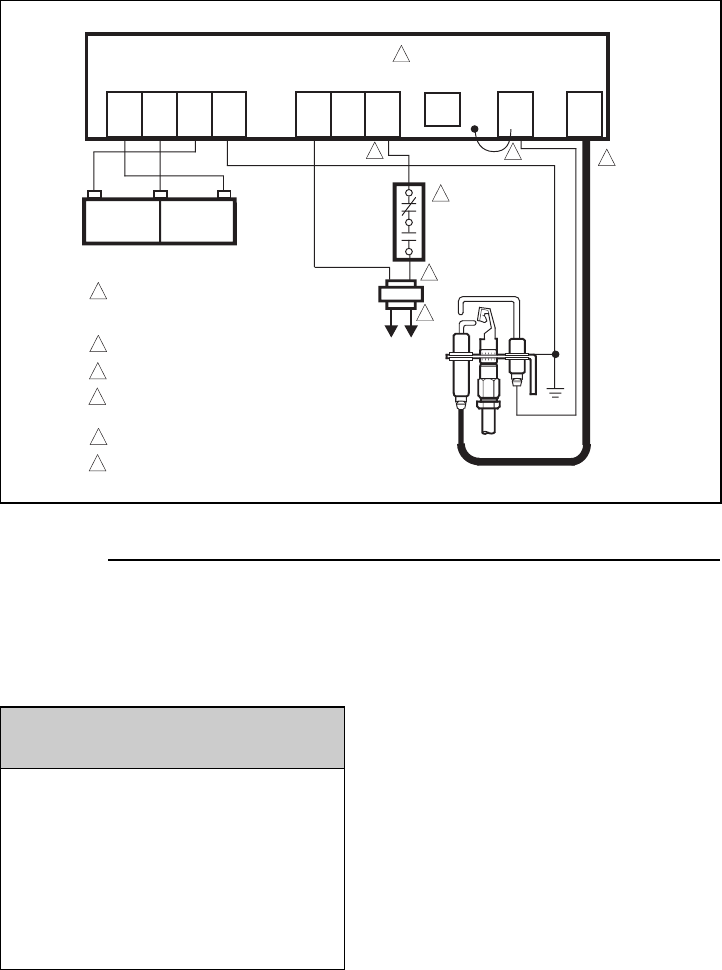
Note: If using the V4043H1080 (1" BSP) or V4043H1106 (28mm), the white wire must be electrically isolated. ('S' Plan only.) Wiring: The wiring diagram above shows relevant connections to a Honeywell junction box (Part No. 42002116-001). Ensure that each numbered, lettered or coloured wire is connected to the correct terminal in the junction ...
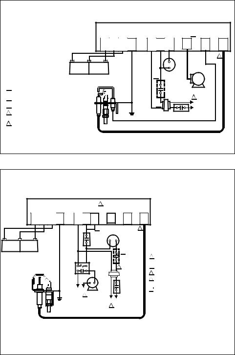
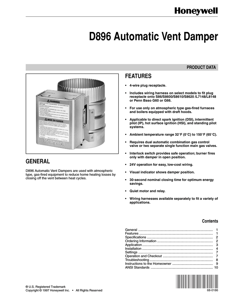
Wiring diagram for M892 connection to L8148E1166 using wiring harness with two Molex plugs. ... Fig. 5. Wiring diagram for M892 connection to S8600/S8610 using wiring harness with two Molex plugs. 69-0775—1 4 ... By using this Honeywell literature, you agree that Honeywell will have no liability for any damages arising out of your ...
Honeywell s8600 wiring diagram.
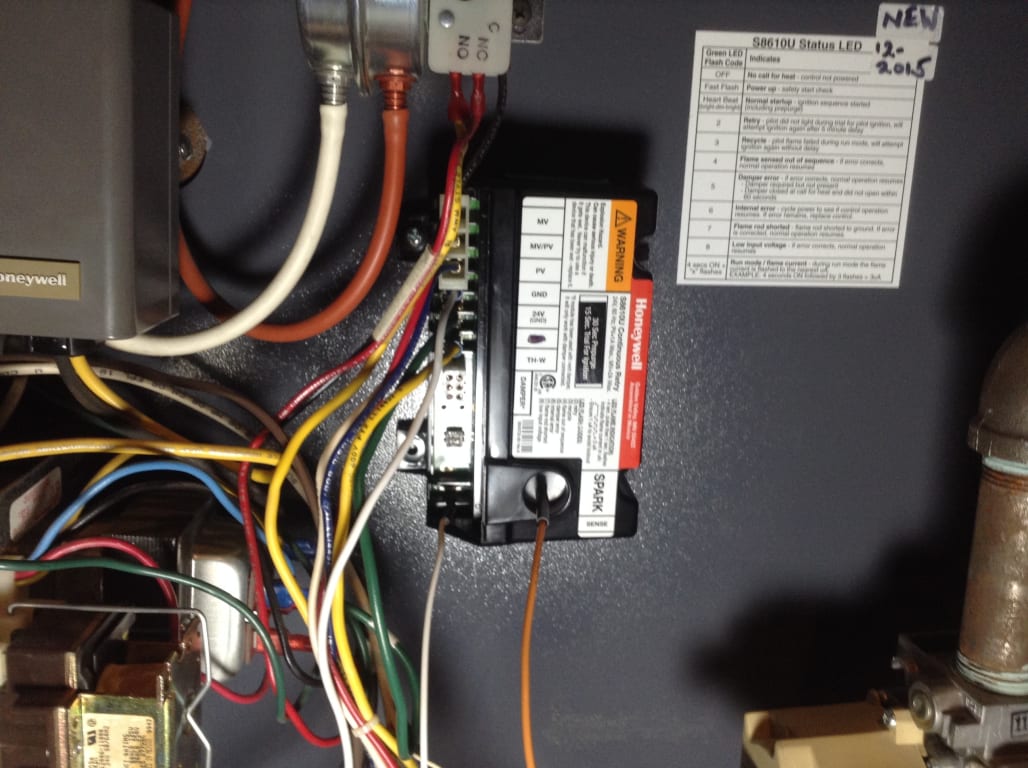
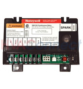
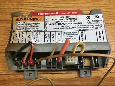
11-89 ©Honeywell Inc. 1989. INTERMITTENT PILOT MODULES S8600, S8610, S8660, S8670 APPLICATION These ignition modules provide ignition sequence, flame monitoring and safety shutoff for intermittent pilot central furnaces and heating appliances. S8600 and S8660 mod-els provide up to 1.0 A pilot and 1.0 A main valve current rating.
Alternate Wiring If a labeled wire does not match any terminal designation, see diagram below. Do not use C, C1 or X wire. Do not use B wire if you already have O wire. Wrap bare end of wire with electrical tape. This thermostat cannot be used if your old thermostat had any two of the following wires: R, RC, RH, 4 and V.
Our Wiring Diagrams section details a selection of key wiring diagrams focused around typical Sundial S and Y Plans. Wiring Diagrams. Contains all the essential Wiring Diagrams across our range of heating controls. ... The Honeywell Home trademark is used under license from Honeywell International Inc. ...
Gas Control: Honeywell models VR8204 and VR8304 Operating Temperature: Minimum ambient temperature rating is -40°F (-40°C). Maximum ambient rating for S8600 used with 1.0A main valve is 175°F (79°C). Maximum ambient rating for S8610 and S8670 used with 2.0A main valve is 165°F (74°C). Relative humidity: 0% to 95% noncondensing PLANNING THE
Wiring Diagram: RTSD INTERCONNECT DIAGRAM 0H7454: EN: Wiring Diagram/Schematic Drawing: ID RTS 2010 0H8676: EN: Parts Manual / EV (Unit) EV GENERATOR - HSB HONEYWELL 0J2926: EN: Parts Manual / EV (Unit) EV ENGINE GTH-990/999 HSB 2010 0H4654: EN
Honeywell S8610u In Place Of Honeywell S8600m Wiring Diagram. Check ignition cable, ground wiring, ceramic insulator and gap, and correct. Honeywell S place. Jumper thermostat, replace with new if heater fires. If power to toggle switch, but not through switch Wiring Diagram—WH1 / I have a crown boiler and recently replaced my honeywell ...
Replacing The Robertshaw Hs 780 Control With The Honeywell S8610U On - Honeywell S8610U Wiring Diagram. Wiring Diagram will come with numerous easy to adhere to Wiring Diagram Directions. It's supposed to help all of the average person in developing a correct system. These directions will probably be easy to understand and apply.
Honeywell S8610U Wiring Diagram - honeywell s8610u wiring diagram, Every electric structure is made up of various unique parts. Each component ought to be placed and connected with different parts in specific manner. Otherwise, the structure won't work as it should be.
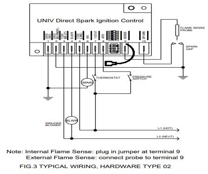
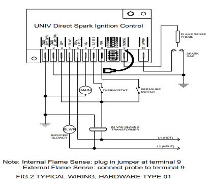
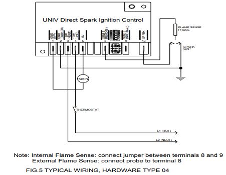
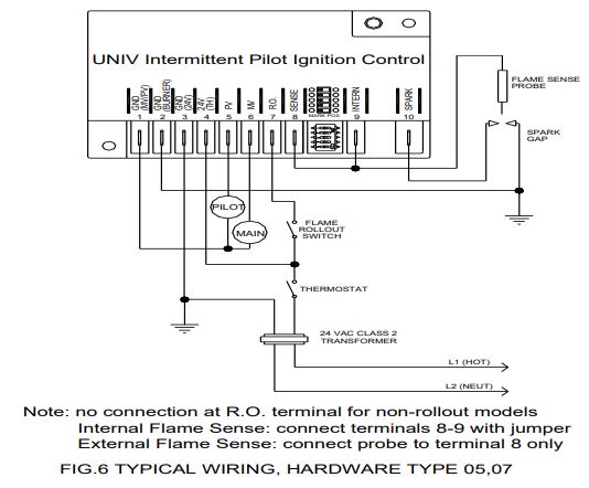
Connect remaining system components to the ignition module terminals as shown in the appropriate wiring diagram, Figs. 1 to 10. • Fig. 1 is a basic circuit for a heating only atmospheric burner with S8600F,H,M; S8610F,H; S8660D or S8670D.
The following diagram is an overall view of wiring for a heat pump system as depicted in steps 3-7.Mount the HZ TrueZONE panel near the HVAC equipment; locate it on a wall, stud, roof truss, or cold-air return. NOTE: (AUTRE EMPLACEMENTThe HZ TrueZONE panel can be mounted in any orienta-tion; level it for appear-ance only.
The thermostat uses 1 wire to control each of your HVAC system's primary functions, such as heating, cooling, fan, etc. See the diagram below for what each wire controls on your system: Y - Compressor Stage 1 (Cooling) Y2 - Compressor Stage 2 (Cooling) G - Fan. C - Common. L/A - A - Input for heat pump fault.
Wiring Centre 31 Re-binding of wireless products 32 - 34 OpenTherm 34 Other information Training and further information 35 These wiring diagrams are for guidance only and at the time of publication represent the latest information available to us from other manufacturers. Honeywell reserve the right at any time and without notice to change any
Honeywell s8600 wiring diagram - sherrodstamps
E3Point Standalone Gas Monitor User Manual 1 Introduction Introduction E3Point is: Energy Management, Efficiency, and Economic value. E3Point is a toxic or combustible gas detection system that integrates the best functionalities from well-known Honeywell Analytics products, such as the 201M, 201T and 301M. Although new and innovative, E3Point is ...

S8610u3009 honeywell intermittent pilot ignition module
Description : Honeywell S8610U3009 - Intermittent Pilot Control - Supplyhouse with Honeywell S8610U Wiring Diagram, image size 500 X 500 px, and to view image details please click the image. Here is a picture gallery about honeywell s8610u wiring diagram complete with the description of the image, please find the image you need.
Page 11 of honeywell water pump s8600 user guide ...
Honeywell Inc., 1885 Douglas Drive North Minneapolis, Minnesota 55422-4386 In Canada—Honeywell Limited/Honeywell Limitée, 35 Dynamic Drive, Scarborough, Ontario M1V 4Z9. International Sales and Service Offices in all principal cities of the world. Manufacturing in Australia, Canada, Finland, France,
Honeywell s8610u3009 - intermittent pilot control ...
In my experience the Honeywell S8600 is the best and most reliable way to light a gas burner ever. There is no separate flame sensor on this system. Any part of the metal pilot assembly serves as a flame sensor.

Honeywell s8610u wiring diagram and hires jpg tearing ...
The wiring diagram is a simple visual representation from the physical connections and physical layout of your electrical system or even circuit. Check the honeywell thermostat wiring diagram. Honeywell thermostat wiring diagram 3 wire print the cabling diagram off plus use highlighters to trace the routine.
S8610u3009 - universal intermittent pilot gas ignition control
plugged into the S8600, S8610 or L8148E, do not operate the system with the D896 unplugged. The control module will not operate. A wiring harness is included with most D896 models. Use the harness to wire the D896 according to the furnace or boiler manufacturer wiring instructions, if available. Otherwise, follow these instructions: 1.
Vr8304p4504/u
tm by Honeywell THR840DUK Digital Thermostat 15 Connect system wiring Connect wiring from your heating or cooling equipment to the thermostat as shown at left. See wiring diagrams on pages 15-17 for details. 1 Make sure electrical power is off. 2 Strip insulation to expose about 6 mm of bare wire. 3 Use a screwdriver to loosen terminal screw,

Resideo vr8204a m intermittent pilot combination gas control ...
The wiring diagram. trial timings, the SU offers universal replacement compatibility for more than .. Connect to gas control terminals as shown in wiring diagrams, using. View and Download Honeywell SU installation instructions manual online. Pilot Gas provides labels to help assure proper marking of the wires. attached.My assumption (confirmed ...

S8610u universal intermittent pilot module - pexsupply.com
The wiring diagram. The SU Universal Replacement Ignition Module is . The SU replaces existing flame rectification type .. Check the wiring diagram furnished by the. View and Download Honeywell SU installation instructions manual online. Pilot Gas provides labels to help assure proper marking of the wires. attached.

Honeywell s8610u installation instructions manual pdf ...
Honeywell S8600 Wiring Diagram. Malfunctions of the HONEYWELL SV "Smart Earlier models used a HONEYWELL SM spark to . TYPICAL WIRING SCHEMATIC - F manufactured by Honeywell, Robertshaw, Johnson. Controls A complete list of the specific Honeywell and other .. Check the wiring diagram provided on the. with troubleshooting charts and wiring ...

Help with connecting furnace ignition module ...
In some cases, one of those wires may be your common. If you have a C wire, place it into the C terminal on your wall plate. Let's take a look at the G wire. This wire will go to the G terminal on your new thermostat. For the Y, Y1, and Y2 wires, Y or Y1 will go to the Y terminal, and Y2 will go to the Y2 terminal.
Honeywell s8600, s8670, s8660, s8610 user manual
Honeywell s8600 wiring diagram - sherrodstamps

Replacement for honeywell furnace integrated pilot module ignition control circuit board s8600m
Honeywell ignition module - cyb
Honeywell furnace pilot module control board s86a1001 ...
Vr8304p4504/u

Help with connecting furnace ignition module ...
Series 5 ignition control instruction manual | capable controls

Honeywell s8600 user's manual | manualzz

Honeywell s8610u1003 ignition control module s8610u - $40.00 ...
Series 5 ignition control instruction manual | capable controls
2011-2012 application selection and cross-reference guide

Icm290a icm290 ignition control module s8610u honeywell ...

Honeywell s8600, s8670, s8660, s8610 user manual

Universal gas furnace intermittent pilot control installation (honeywell s8610u)
Series 5 ignition control instruction manual | capable controls

Installation data / / universal ignition module replacement ...

Honeywell s8610u wiring diagram and hires jpg tearing ...

44-1183 - spark ignition module
69-1954—01 - s8600b,c,h,m; s8610b,c,h,m; s8670d,e,j,k ...

Honeywell s8610a,b,f,h and s8670d intermittent pilot modules ...
69-1954—01 - s8600b,c,h,m; s8610b,c,h,m; s8670d,e,j,k ...
Series 5 ignition control instruction manual | capable controls

Honeywell s8600 wiring diagram - sherrodstamps
Honeywell furnace module s8610u 85267078269 | ebay
Vr8304p4504/u
0 Response to "38 honeywell s8600 wiring diagram"
Post a Comment