37 msd 3 step wiring diagram
Male Connector for fuel This is a Johnson & Evinrude Outboard Female 2-Prong Fuel Line Connector. 2% positive. 90 View Details. (92 x 66 mm) Displ. 1994 Evinrude 175 Hp Wiring Diagram Today Step 3. 2 Stroke Mercury Outboard Wiring Diagram Schematic. This Item: Johnson Evinrude Fuel Connector Kit Assembly 0438793. 75. 10 (0) . Dual Flow Motor ... Note: The MSD 7AL-3 will retard the ignition timing approximately 4° compared to other MSD Ignitions. Read online or download PDF • Page 9 / 12 • MSD 7AL-3 Ignition Control Installation User Manual • MSD For the car. Choose the appropriate wiring diagram from the reverse side and wire as shown.
Msd 3 Step Wiring Diagram - wiring diagram is a simplified standard pictorial representation of an electrical circuit. It shows the components of the circuit as simplified shapes, and the capacity and signal contacts amid the devices.

Msd 3 step wiring diagram
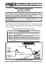
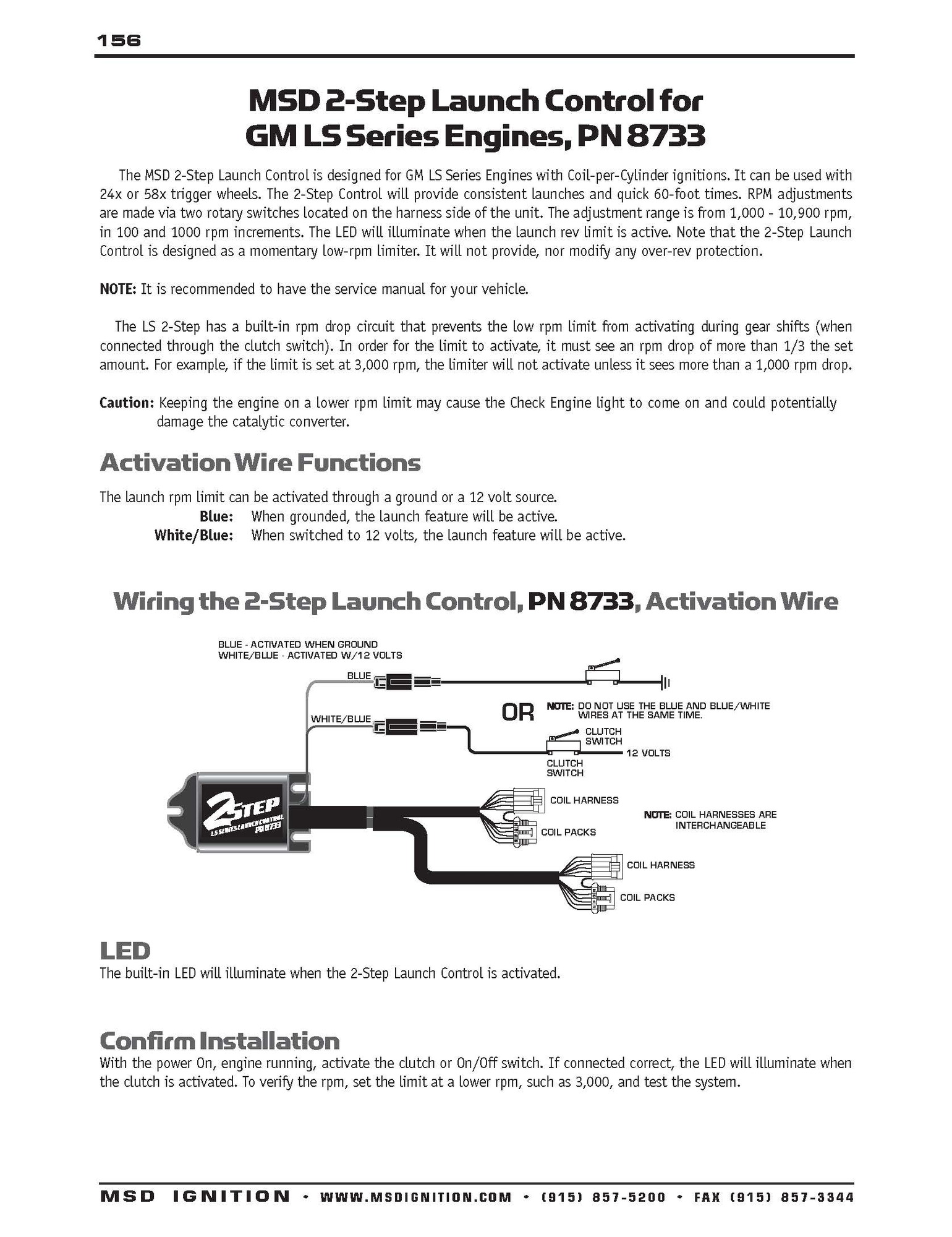
MSD Module Selectors Two Step, PN 8739 Three Step, PN 8737 Parts Included: 1 - Module Selector 4 - Mounting Screws Note: Do NOT use solid core spark plug wires with any MSD component. 1 - Parts Bag, Wiring Terminals The MSD Module Selectors provide the ability to switch between two or three different rpm or degree modules. Page 1 MSD Module Selectors Two Step, PN 8739 Three Step, PN 8737 Parts Included: 1 - Parts Bag, Wiring Terminals 1 - Module Selector 4 - Mounting Screws Note: Do NOT use solid core spark plug wires with any MSD component.; Page 2 INSTALLATION INSTRUCTIONS REV LIMITER STEP MODULE SELECTOR PN 8739 BLACK AUTOTRONIC CONTROLS CORPORATION 1490 HENRY BRENNAN DR, EL PASO, TX 79936 MODULE 2 MODULE 1 ... Carrier 2 Stage Heat Pump Sveas Co. Use these diagrams with caution and at your own risk as we are not responsible for Unlike a pictorial diagram, a wiring diagram uses abstract or simplified shapes and lines to show components. 2018 Tiffin System Diagrams. Oct 23, 2021 · Mercial fire alarm system wiring diagram and addressable smoke.
Msd 3 step wiring diagram. Uses and Application of Transformer. The most important uses and application of Transformer are:. It can rise or lower the leve l of level of Voltage or Current ( when voltage increases, current decreases and vice virsa because P =V x I, and Power is same ) in a n AC Circuit. Msd 3 Step Wiring Diagram from i2.wp.com To properly read a wiring diagram, one has to find out how typically the components in the program operate. For example , if a module will be powered up also it sends out a new signal of 50 percent the voltage plus the technician will not know this, he'd think he offers a problem, as this individual ... Note: The MSD 7AL-3 will retard the ignition timing approximately 4° compared to other MSD Ignitions. After installation, the timing should always be checked and adjusted at idle and total timing. RAS ON/OFF Figure 5 Primary Wiring to a Mallory Unilite Distributor. NOTE: ALL 3-WIRE MALLORY DISTRIBUTORS CONNECT THIS WAY. Msd Two Step Wiring Diagram. By | February 24, 2016. 0 Comment. 2 step wiring question help yellow bullet forums msd 8737 rpm module selector installation instructions jegs mounting 8732 rev control for digital 6al user manual page 4 ignition 8739 pdf manualslib two pages also three will a work with transmission ford mustang stangnet and ...
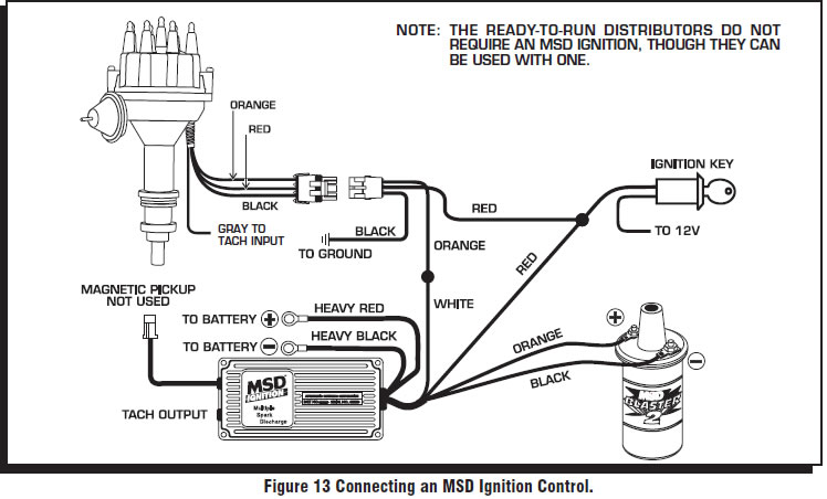
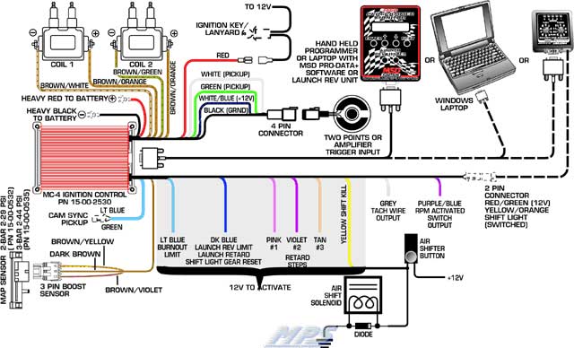
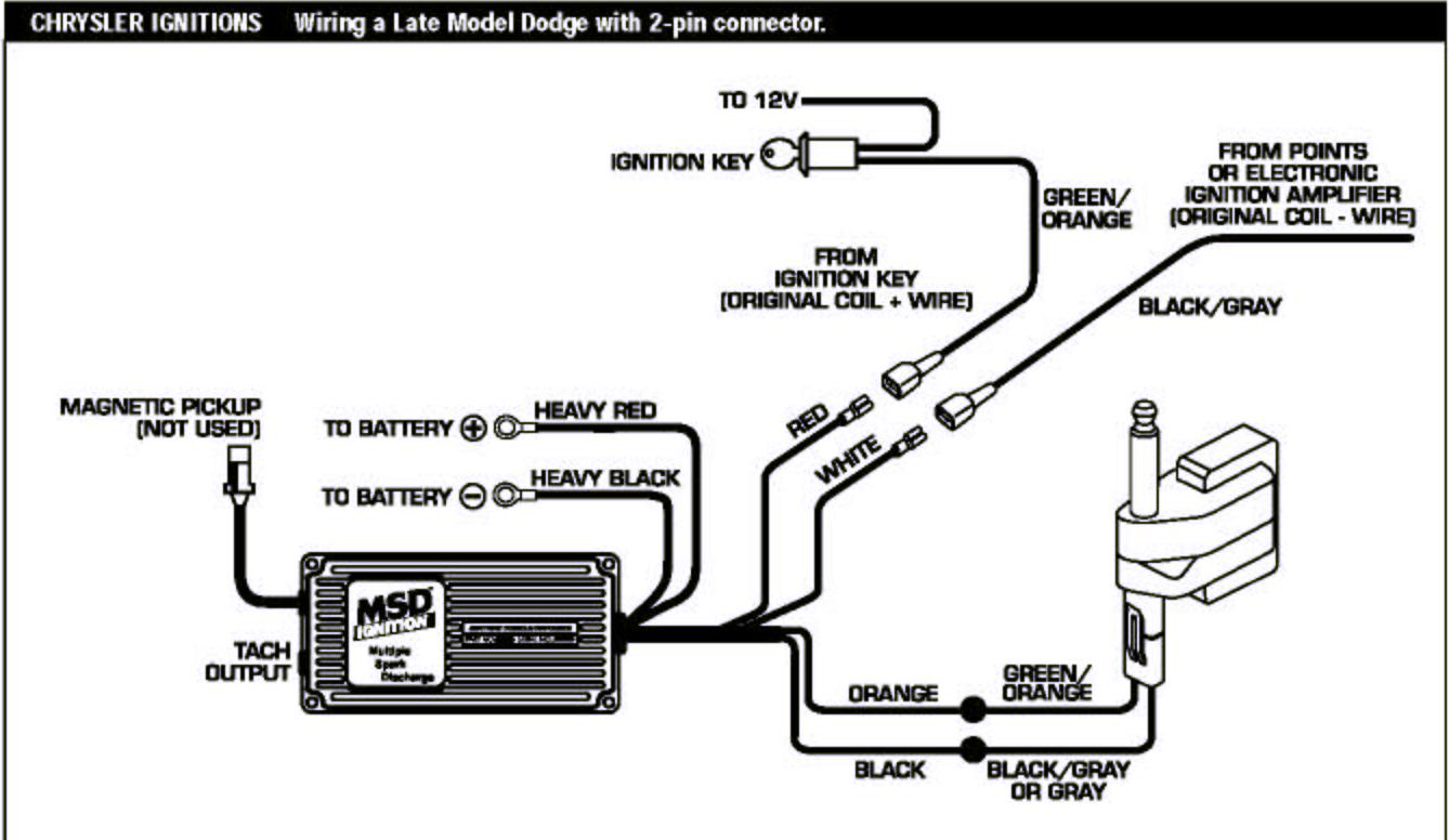
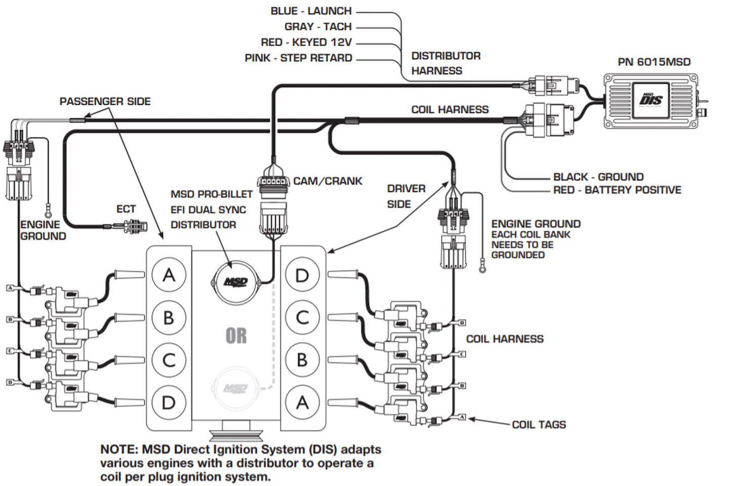
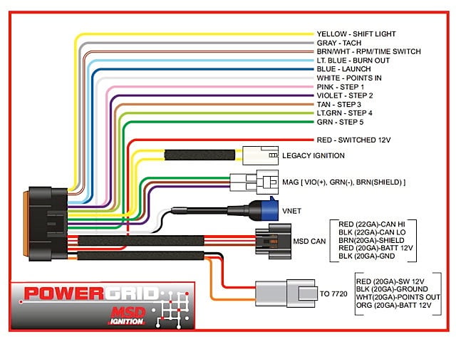
tan - step 3 lt. green - step 4 green - step 5 switched ignition 12v white - points in legacy ignition msd can mag pickup connector + orange note: see pages 10 -12 for schematics showing installation to other msd ignition controls. -black mag pickup connector msd can legacy ignition pink - step 1 violet - step 2 tan - step 3 lt. green - step 4 To help drag racers achieve even more consistency, our engineers have incorporated an adjustable low rpm stage into a Three Step Module Selector! This allows you to make adjustments in 100 rpm increments from the driver's seat! The Launch Control Module features a shielded harness for increased protection against EMI so it can be mounted within easy reach of the driver. This way, as track ... wire that makes electrical contact with the positive coil terminal. This wire connects to the coil negative (-) terminal. This is the ONLY wire that makes electrical contact with the negative coil terminal. There are three circuits that can be used to trigger the MSD Ignition; a Points circuit (the White wire), a Magnetic Pickup circuit (the Green A wiring diagram is a type of schematic which uses abstract photographic icons to show all the interconnections of elements in a system. Msd 6al 2 ignition control pn 6421. Msd 6al with 2 step wiring diagram use wiring diagram msd 3 step wiring diagram schema diagram database. Symbols that represent the components in the circuit as well as ...
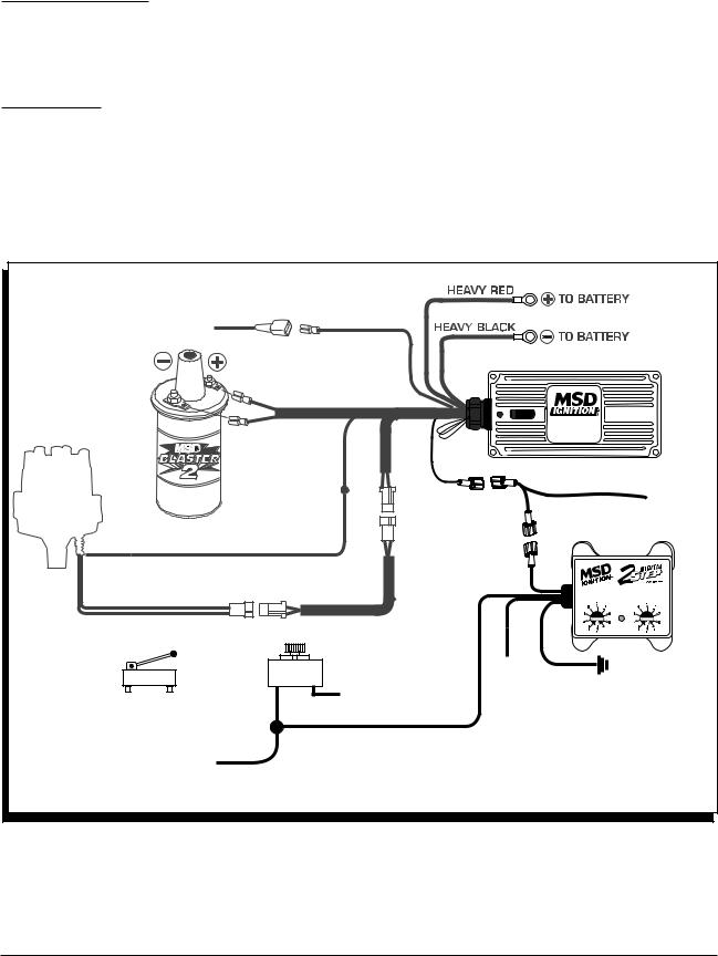
MSD Module Selectors Two Step, PN 8739 Three Step, PN 8737 Parts Included: 1 - Module Selector 4 - Mounting Screws Note: Do NOT use solid core spark plug wires with any MSD component. 1 - Parts Bag, Wiring Terminals The MSD Module Selectors provide the ability to switch between two or three different rpm or degree modules. Msd Wiring Diagram - Wiring Diagrams Hubs - Msd Ignition Wiring Diagram. You can often count on Wiring Diagram as an crucial reference that may assist you to save money and time. Using the assist of this book, you are able to easily do your personal wiring assignments. No matter what you will need it for, you can often locate a list of. Join the Holley Family. Stay up to date with the latest releases, events, promotions and more. MSD 2 Step Clutch Wiring Diagram. Jump to Latest Follow 1 - 15 of 15 Posts. D. DougA · Premium Member. Joined Jul 14, 2002 · 4,538 Posts . Discussion Starter · #1 · Feb 23, 2010. Only show this user ...
The MSD 6014 LS Ignition controller works with 24x/1x, 58x/4x and crank/cam configurations. It auto detects the correct configuration based on the reluctor wheel pattern, so there is no need to select one. It provides six pre-programmed (non-editable) timing tables for stock engines, three customizable 3-D tables and one customizable timing plot.

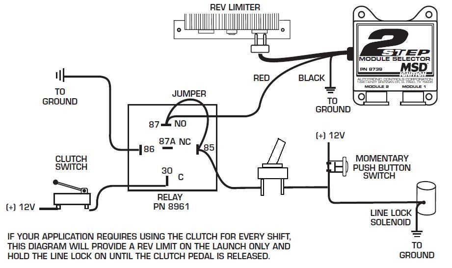
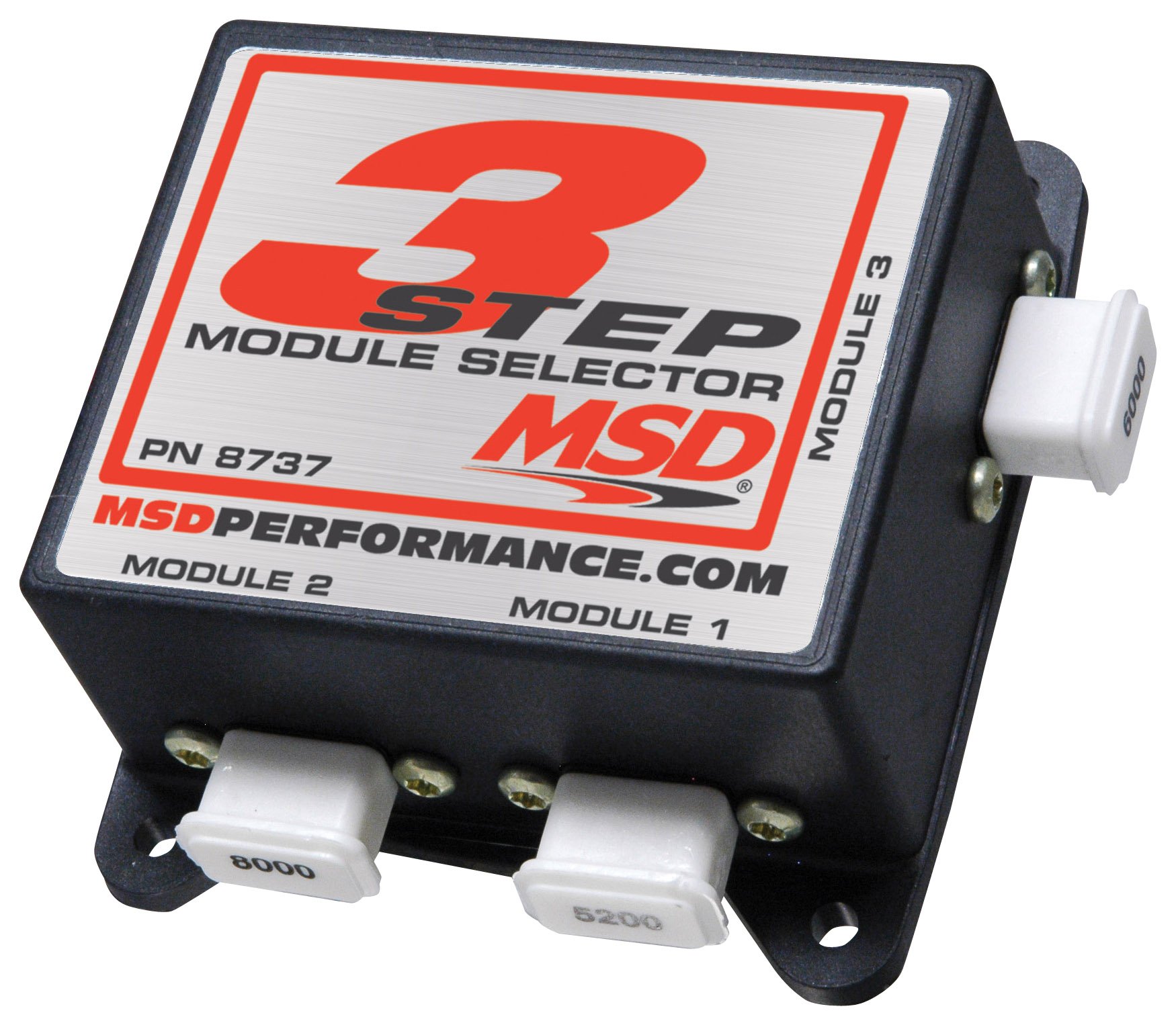
As an example, we'll use a drag car with a Three Step Module Selector plugged into the rpm socket of a 7AL-2 Ignition. The different rpm modules are activated when 12 volts are applied to a corresponding wire. By connecting one wire to the line-lock circuit, one module will be activated during the burnout. This helps keep tire temperatures consistent. When the line-lock button is released ...
Msd Pn 8970 Wiring Diagram. That is why we have assembled the MSD Ignition Wiring Diagrams and Tech Notes Book. 3-Stage Retard, PN , and Multi-Step Retard, PN Red. Page 1. 3-Stage Retard PN IMPORTANT: Read the instructions before attempting the installation. Parts Included: 1 - 3-Stage Retard Control 4 - Mounting.

Dec 01, 2021 · 3 pin ignition coil wiring diagram. 3 pin ignition coil wiring diagram. 3 pin ignition coil wiring diagram ...

Here is an external wiring diagram for the V3.0 board. V2.2 wiring is identical except that you will connect the MSD white wire to pin 25 instead of 36. Note that the fuses and relays are already in the stock wiring, so you will not need to change these.
msd rpm module wire diagram 3 stage wiring diagram host Architectural wiring diagrams take effect the approximate locations and interconnections of receptacles, lighting, and unshakable electrical services in a building. Interconnecting wire routes may be shown approximately, where particular receptacles or fixtures must be on a common circuit.
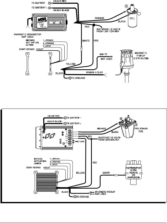
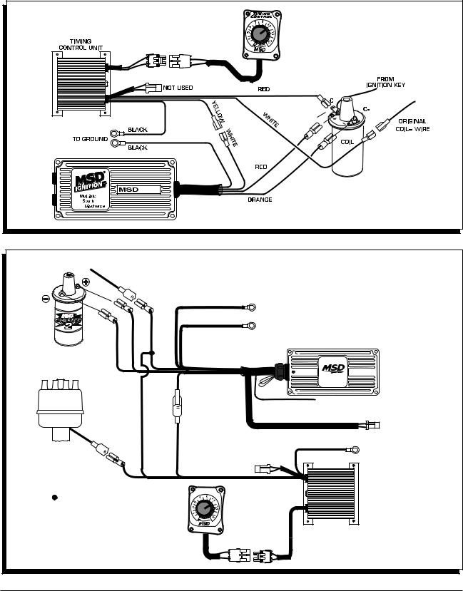
STEP CONTROL WIRES GRAY This wire activates the Step Retard when it is removed from ground. Note: If the Step Retard is not going to be used, ... Figure 10 Wiring an MSD 10 PLUS with a Mag Pickup. INSTALLATION INSTRUCTIONS MSD IGNITION • www.msdignition.com • (915) 857-5200 • FAX (915) 857-3344
4 INSTALLATION INSTRUCTIONS AUTOTRONIC CONTROLS CORPORATION • 1490 HENRY BRENNAN DR., EL PASO, TEXAS 79936 • (915) 857-5200 • FAX (915) 857-3344 WIRING GENERAL WIRING INFORMATION Wire Length: All of the wires of the MSD Ignition may be shortened as long as quality connectors are used or soldered in place.

Step 3 Remove the distributor cap from the distributor. Do not remove the spark plug wires or coil wire at this time. Make sure the rotor blade points to the mark made on the distributor housing (from Step 2). If it does not, repeat Step 2 until the timing mark lines up (again) with the TDC mark on the timing tab.

MSD Three-Step Module Selectors. MSD 3-step module selectors are designed for great versatility. They feature three built-in rev limiters--one for burnout, one for starting line launch, and one for high end. These selectors use the MSD plug-in rpm modules. Recommended for You.
wire the 2-Step rev limit and the LED will turn off. 3-STEP If you prefer to have three different rev limits, a second PN 8732 could be used to provide a third rev limit, such as for use during the burnout. MSD • WWW.MSDPERFORMANCE.COM • (915) 855-7123 • FAX (915) 857-3344 ONLINE PRODUCT REGISTRATION: Register your MSD product online.
The MSD 2-Step Launch Control is designed for Ford Modular Engines with Coil-on-Plug ignitions. ... Figure 3 Wiring the Launch Activation Wire. ACTIVATES WITH 12 VOLTS OR GROUND WHITE BLUE BLUE GROUND TAN RED GRAY BLACK NOTE: IF THE LED DOESN'T TURN ON, AS DETAILED IN STEP 5, FOLLOW THIS DIAGRAM BY SWAPPING THE 8 PIN CONNECTORS. WHITE BLUE BLUE ...
INSTALLATION INSTRUCTIONS 3 AUTOTRONIC CONTROLS CORPORATION • 1490 HENRY BRENNAN DR., EL PASO, TEXAS 79936 • (915) 857-5200 • FAX (915) 857-3344 Figure 4 Wiring an MSD 6 Series Ignition with a Mag Pickup. Figure 5 Wiring an MSD 7 Series Ignition with Points/Amplifier.

Here is the install of the MSD 3 Step... This one is for the analog 6AL box that's older. MSD also makes one of these for the digital 6AL box.Thanks For Wa...
Msd 3 Step Wiring A wiring diagram usually gives recommendation more or less the relative perspective and arrangement of devices and terminals on the devices, to help in building or servicing the device. This is unlike a schematic diagram, where the pact of the components' interconnections on the diagram usually does not tie in to the ...
3. After cutting the loop(s), turn the wire ends away from each other so they cannot come into contact. Install the cover and screw. WIRING GENERAL WIRING INFORMATION Wire Length: All of the wires of the MSD Ignition may be shortened as long as quality connectors are used or soldered in place.
I have it conected to my 2 step so the transbrake and 2 step are activated at the same time. The solenoid will engage and release when the rpms are low but if I push the transbrake button and put the peddle to the floor the car comes up on the 2 step but when I release the button the car doesn't move. Could it be low amperage or just a wiring ...

Description: The Hot Rod Garage - Wiring Information with regard to Transbrake Wiring Diagram, image size 726 X 521 px, and to view image details please click the image.. Actually, we also have been remarked that transbrake wiring diagram is being one of the most popular topic at this moment. So that we attempted to locate some great transbrake wiring diagram picture for you.

Carrier 2 Stage Heat Pump Sveas Co. Use these diagrams with caution and at your own risk as we are not responsible for Unlike a pictorial diagram, a wiring diagram uses abstract or simplified shapes and lines to show components. 2018 Tiffin System Diagrams. Oct 23, 2021 · Mercial fire alarm system wiring diagram and addressable smoke.

Page 1 MSD Module Selectors Two Step, PN 8739 Three Step, PN 8737 Parts Included: 1 - Parts Bag, Wiring Terminals 1 - Module Selector 4 - Mounting Screws Note: Do NOT use solid core spark plug wires with any MSD component.; Page 2 INSTALLATION INSTRUCTIONS REV LIMITER STEP MODULE SELECTOR PN 8739 BLACK AUTOTRONIC CONTROLS CORPORATION 1490 HENRY BRENNAN DR, EL PASO, TX 79936 MODULE 2 MODULE 1 ...
MSD Module Selectors Two Step, PN 8739 Three Step, PN 8737 Parts Included: 1 - Module Selector 4 - Mounting Screws Note: Do NOT use solid core spark plug wires with any MSD component. 1 - Parts Bag, Wiring Terminals The MSD Module Selectors provide the ability to switch between two or three different rpm or degree modules.


0 Response to "37 msd 3 step wiring diagram"
Post a Comment