37 moore machine state diagram
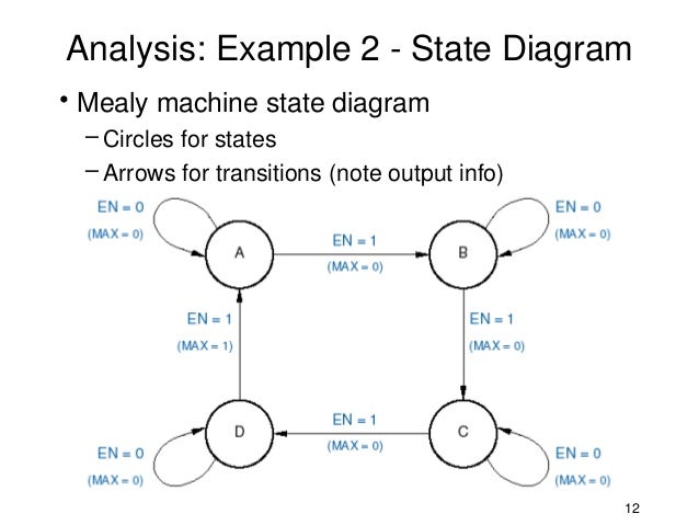
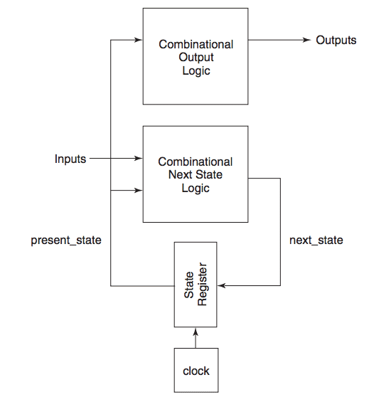
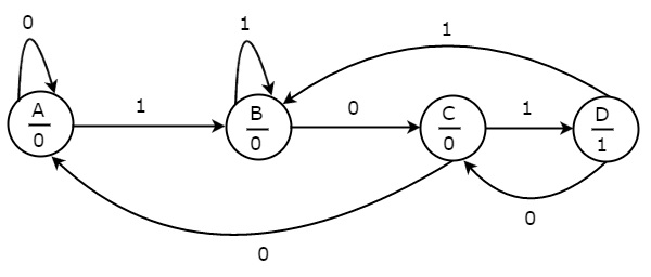
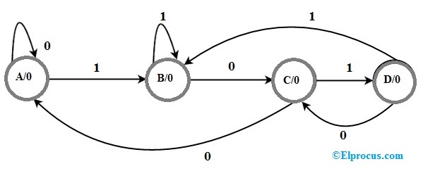
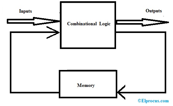
A state machine is a behavior model. It consists of a finite number of states and is therefore also called finite-state machine (FSM). Based on the current state and a given input the machine performs state transitions and produces outputs. There are basic types like Mealy and Moore machines and more complex types like Harel and UML statecharts. The Moore state machine state diagram is shown below. In the above state, the diagram includes four states like a mealy state machine namely A, B, C, and D. the four states as well as individual outputs are placed in the circles. State Diagram of Moore State Machine.
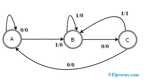
Mealy state diagram of a JK flip-flop CLK a b Q Q J K 10/0, 11/0 01/1, 11/1 00/1 10/1 00/0 01/0 Inputs: J K Outputs: Q State label output (Q) inputs (JK) Note that here the input values are shown in binary rather than Boolean expressions. This can be done for Moore state diagrams as well. E1.2 Digital Electronics 1 10.15 13 November 2008

Moore machine state diagram
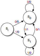
-STATE DIAGRAM EX. • Consider the simple bit flipper looked at the in previous chapter. How would a state diagram be formed? • Below is one possible way of drawing the state diagram for the bit flipper. • Since the bit flipper is a Moore machine, the state diagram can also be S0 S1-/1 … Mealy vs. Moore. • Moore. – Out = F (Current state). – Next state = F (Inputs, current state) Draw a state graph for the Lock-FSM. A small. Diagram –. Moore Machine – A moore machine is defined as a machine in theory of computation whose output values are determined only by its current state. Here are diagrams of a Mealy state machine ... Figure 5: State diagram for „1010‟ sequence detector using Moore machine (with overlapping) The Moore machine can be designed same way as Mealy machine using Verilog. Only difference is that in case of Moore machine there are 5 states. Instead of output branch, there is a output state in case of Moore Machine.
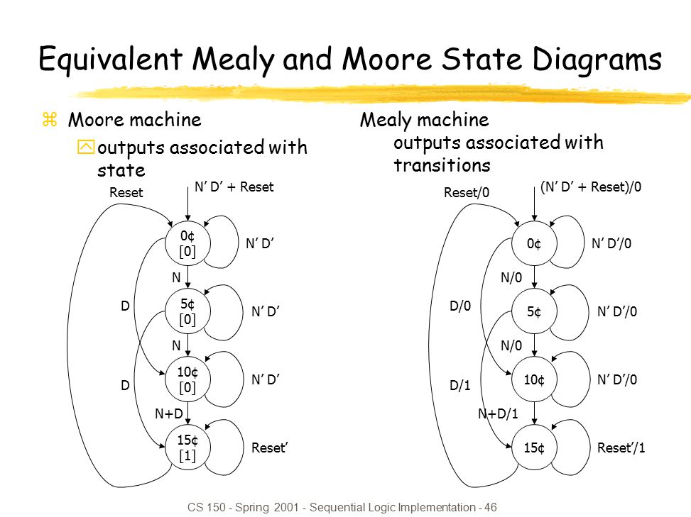
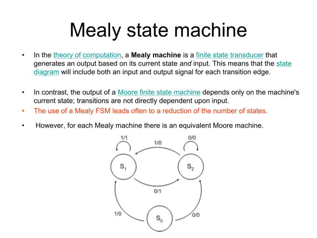
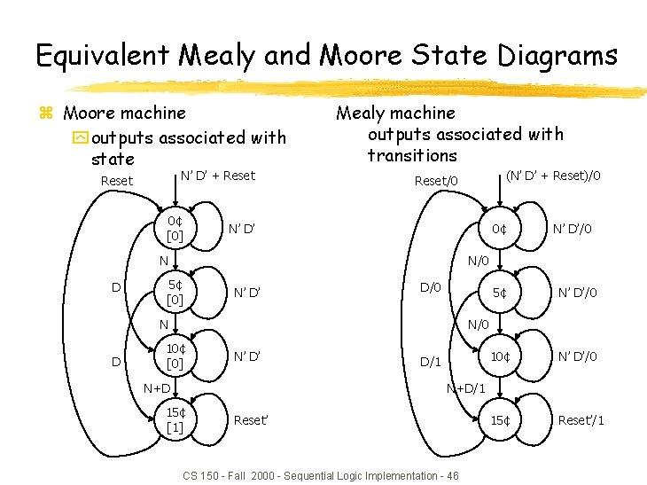
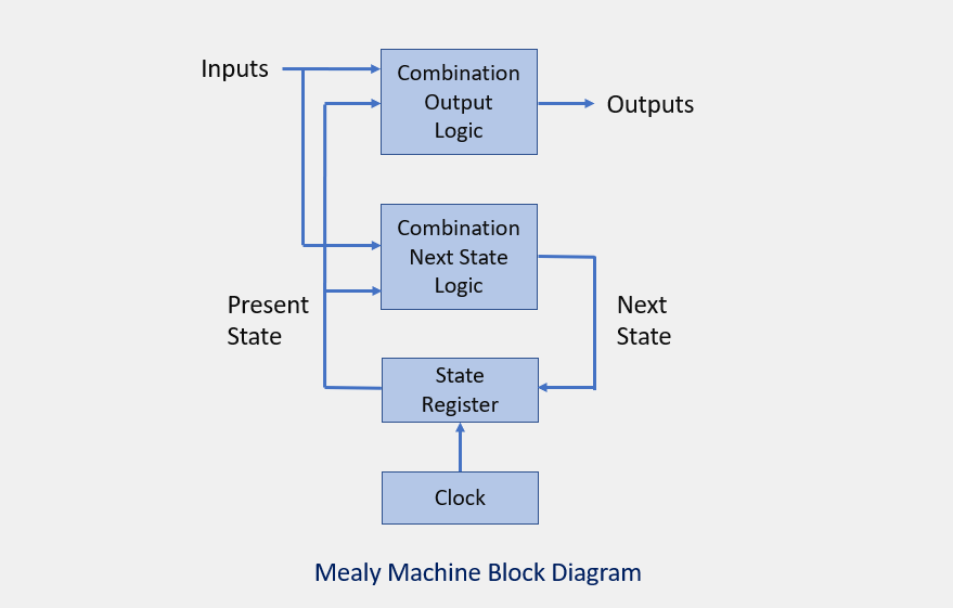
Moore machine state diagram. One of the states in the previous Mealy State Diagram is unnecessary: Note: The Mealy Machine requires one less state than the Moore Machine! This is possible because Mealy Machines make use of more information (i.e. inputs) than Moore Machines when computing the output. Having less states makes for an The state machine is a circuit that reacts to one or more inputs that direct it to move into one of a number of possible states, depending on the value of the current state and the value of the current input. State machines are based on either the Moore or Mealy machines. The state transition diagram is drawn to represent state machine ... Moore Machine State Diagram, Mealy Machine State Diagram, Karnaugh Maps D FLIP-FLOP BASED IMPLEMENTATION: SHIFT REGISTERS: Serial In/Shift Left,Right/Serial Out Operation >> CS302 - Digital Logic & Design. Lesson No. 33. STATE ASSIGNMENT. Each state in a sequential circuit is identified by a unique combination of binary bits. The state diagram of the above Mealy Machine is −. Moore Machine. Moore machine is an FSM whose outputs depend on only the present state. A Moore machine can be described by a 6 tuple (Q, ∑, O, δ, X, q 0) where −. Q is a finite set of states.. ∑ is a finite set of symbols called the input alphabet.. O is a finite set of symbols called the output alphabet.
Draw the state diagram for a Moore machine based 001 detector. 2. Draw the state diagram for a Moore machine based 11010 detector. 3. Sketch out the Verilog code for each of these detectors (001, and 11010). 4. Sketch out the Verilog code for a 16 bit shift register with parallel load. 5. A finite-state machine (FSM) or finite-state automaton (FSA, plural: automata), finite automaton, or simply a state machine, is a mathematical model of computation.It is an abstract machine that can be in exactly one of a finite number of states at any given time. The FSM can change from one state to another in response to some inputs; the change from one state to another is … So, we don't need to split this state in Moore machine. Transition table for Moore machine will be: Transition diagram for Moore machine will be: Example 2: Convert the following Mealy machine into equivalent Moore machine. Solution: Transition table for above Mealy machine is as follows: The state q1 has only one output. The state diagram for Moore Machine is. Transition table for Moore Machine is: In the above Moore machine, the output is represented with each input state separated by /. The output length for a Moore machine is greater than input by 1. Input: 010. Transition: δ (q0,0) => δ(q1,1) => δ(q1,0) => q2. Output: 1110(1 for q0, 1 for q1, again 1 for ...
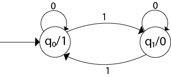
The state diagram for a Moore machine or Moore diagram is a diagram that associates an output value with each state. Moore machine is an output producer. Relationship with Mealy machines. As Moore and Mealy machines are both types of finite-state machines, they ... Nov 20, 2019 · Note: Number of states in mealy machine can’t be greater than number of states in moore machine. Example: The Finite state machine described by the following state diagram with A as starting state, where an arc label is x / y and x stands for 1-bit input and y stands for 2- … If in a Moore machine, the output only depends on the current state Then why does the table for states F and H say the output is Stack Exchange Network Stack Exchange network consists of 178 Q&A communities including Stack Overflow , the largest, most trusted online community for developers to learn, share their knowledge, and build their careers. Figure 5: State diagram for „1010‟ sequence detector using Moore machine (with overlapping) The Moore machine can be designed same way as Mealy machine using Verilog. Only difference is that in case of Moore machine there are 5 states. Instead of output branch, there is a output state in case of Moore Machine.
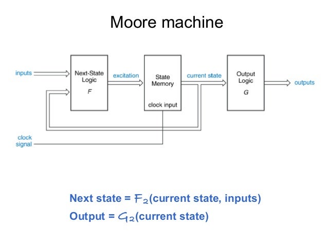
Mealy vs. Moore. • Moore. – Out = F (Current state). – Next state = F (Inputs, current state) Draw a state graph for the Lock-FSM. A small. Diagram –. Moore Machine – A moore machine is defined as a machine in theory of computation whose output values are determined only by its current state. Here are diagrams of a Mealy state machine ...
-STATE DIAGRAM EX. • Consider the simple bit flipper looked at the in previous chapter. How would a state diagram be formed? • Below is one possible way of drawing the state diagram for the bit flipper. • Since the bit flipper is a Moore machine, the state diagram can also be S0 S1-/1 …


0 Response to "37 moore machine state diagram"
Post a Comment