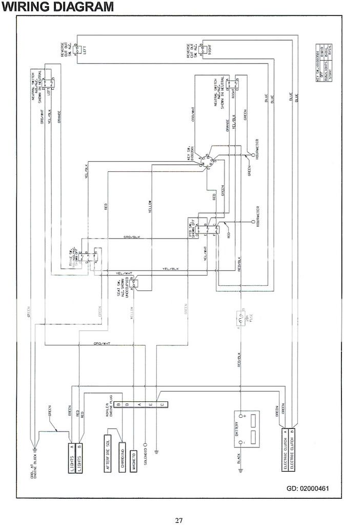
37 hour meter wiring diagram
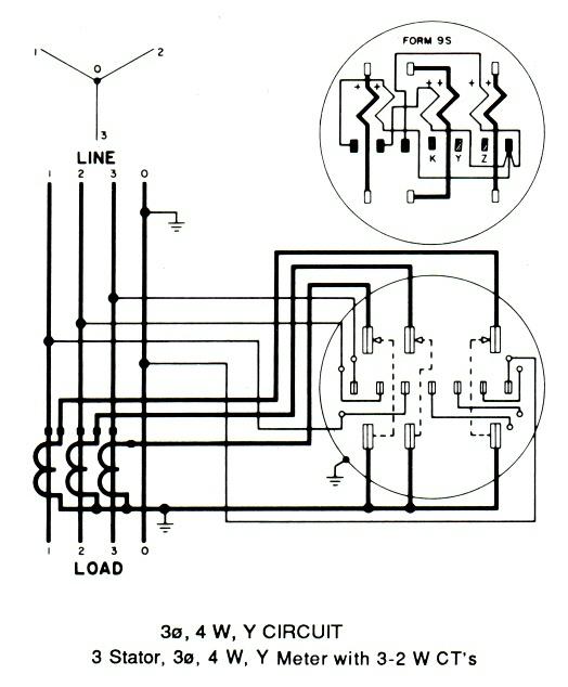
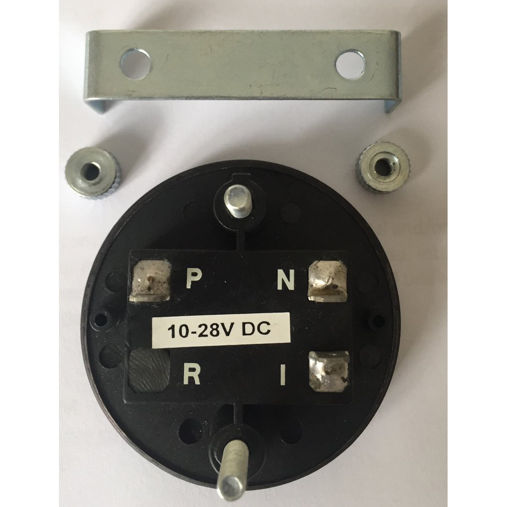
3 Phase, 4 Wire - Form 14K. Click here to view and print the full size diagram. Purchase your meters and. parts with just a click. Shop now. Learn the steps for a flawless installation from start to finish. View Now. the LM Series hour meter is identical to the number of active terminals on the hour meter (either 2, 3, or 4). An equivalent wire may also be used. If the hour meter is mis-wired, no product damage will occur under any mis-wired condition. FIGURE 1. WIRING DIAGRAM Pin + V+ operating voltage Pin - V - common (ground)
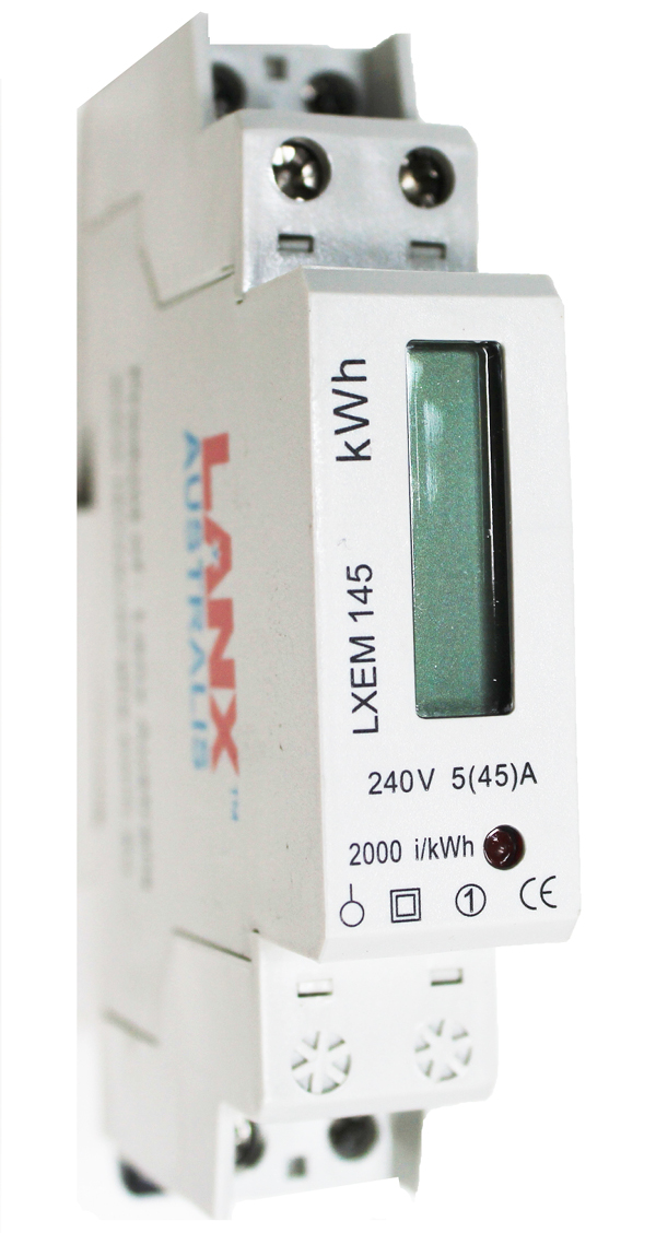
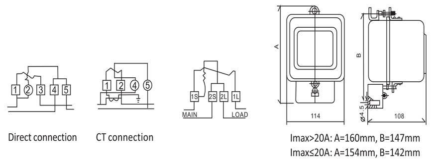
Lt Ac Three Phase Four Wire Panel Mounted Static Kwh Meter. Advanced Installation Of D103 3 Phase Lines Energy Meter Main Smart Maic Support. Cur Transformer Electricity Meter Wiring Diagram Kilowatt Hour Three Phase Electric Power Png 625x690px. China Dt862 2 Three Phase Four Wire Mechanical Meter Kwh Energy.

Hour meter wiring diagram
That will work, as long as the hour meter is a 220V rated unit.If the meter is 120V,connect 1 leg to a neutral on the compressor or if no neutral,connect it to ground.The other leg will still conect to a motor side terminal on the pressure switch.I know it's not "code" to hook up to ground to power the meter,but in this case,as long as the compressor is grounded,the current is so small through ... Connect the hot wire (usually red) on the back of the hour meter to the run wire on the back of the ignition switch, using a Scotch lock wire connector. Attach the ground wire (usually black) on the back of the meter to the boat's grounding system. Do this by connecting the wire to another ground wire with a Scotch lock, or connecting it to a ... Hobbs Hour Meter Wiring Diagram - wiring diagram is a simplified satisfactory pictorial representation of an electrical circuit. It shows the components of the circuit as simplified shapes, and the knack and signal associates between the devices. A wiring diagram usually gives suggestion virtually the relative point and treaty of devices and ...
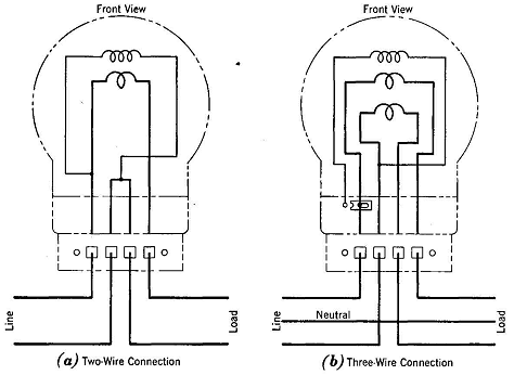
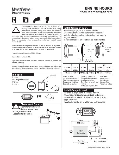
Hour meter wiring diagram. The hour meters are Series Wiring Diagrams Single phase, 2 wire, V system: Connect power wire to one terminal and neutral wire to opposite terminal. Single phase, 3 wire, /V system. Most commonly, people connect the leads coming out of the hour meter to the electric fuel pump, which is designed to supply enough fuel to the injector pump. Attach ... HOUR METER HOUR METER IGNITION SWITCH POWER SUPPLY POWER SUPPLY + +--CONNECTION DIAGRAM Single phase, 2 wire, 120/240 V system: Connect power wire to one terminal and neutral wire to opposite terminal. Single phase, 3 wire, 120/240 V system: Connect any one power wire to one terminal and neutral wire to opposite terminal. Although newer engines often come with display gauges, older ones leave you in the dark. Install an hour meter in just a few steps. Step 1 - Selecting an Hour Meter Model. First, you must select an hour-meter model. Choose your model based on its ruggedness and apparent ease of installation. Having a waterproof hour meter is a plus. Get shopping advice from experts, friends and the community! Hi, I am m also very interest in connecting an Hour Meter and in addition an Amp meter. I notice there has not been an answer posted for this question. So I would like to ask again and ask the proper wire for an Amp meter. Is a wiring diagram available or one for another model that uses the same wiring for the ignition switch?
Description: 3 Phase Kwh Meter Wiring Complete Guide | Electrical Online 4U with regard to Kilowatt Hour Meter Wiring Diagram, image size 945 X 651 px, and to view image details please click the image.. Here is a picture gallery about kilowatt hour meter wiring diagram complete with the description of the image, please find the image you need. Hour Meters Line Guide continued on back page AC HOUR METERS 20000 Series. Features: Polycarbonate, shock resistant, tamper-proof case • Totally sealed • Single phase, synchronous, permanently lubricated motor • Custom logo dials, screw terminal, wire lead or 1/4 in blade terminals, special wire lengths Benefits: From testing purposes to ... opposite terminal to neutral wire. Hour meter is not to be connected to the high leg. Single-phase 240V System: 2-Wire Connect one terminal to power wire; opposite terminal to neutral wire, Single-phase 120/240V System: 3-Wire The hour meter is to be connected across two high sides of the line. The meter is not to be connected to the neutral wire. ENM Hour Meter T39AA Dimensional Diagram · ENM T39AA Wiring Diagram. ENM 6-Digit Electronic LCD Two - Hour Meter 8 - 32V DC - Round SAE Bezel -. 21 records found. Hour Meters: D DIN Rail Time and Pulse Meter. # Download. Hour Meters: T55 Electro-Mechanical Hour Meter. # Download. ENM's series T56 LCD Vibration Activated Hour Meter.
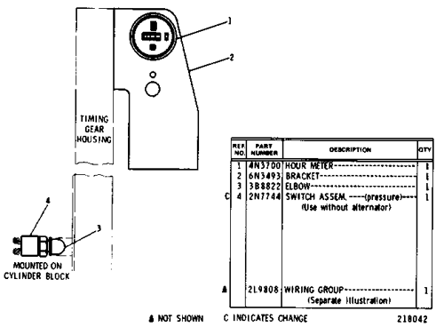
3. Insert the hour meter. Use a marker to mark the holes on each side of the meter. Remove the hour meter. 4. Drill the holes with a 5/32" drill bit. 5. Remove the masking tape and install the hour m Remove the cover from the wire dis eter with the provided hardware. 6. tribution panel ond from right.) 7. 8. istribution panel cover. Fasten wires https://www.amazon.com/gp/product/B00PKDR2WG/ref=as_li_tl?ie=UTF8&tag=supremetools-20&camp=1789&creative=9325&linkCode=as2&creativeASIN=B00PKDR2WG&linkId=5e0... They are both together coming from the meter but then seperate. I am trying to put this 318 back together and don't know where where these black wires go. Any help would be great. Thanks much: Dave: Peter - The wiring diagram shows an orange wire coming off the time delay control module connecting to one of the wires. Sangamo Schlumberger Kilo Watt Hour Meter. Sangamo weston model 12 test meter s29 three phase electricity wiring diagrams s 3 watthour db492a manualzz chapter 51 watt meters and energy handcrafted electric lamp schlumberger kilo hour electrical old style s309 2 100a round pattern time swich single diagram gas unexplained power consumption ecn ge portable induction type 1b5y history clocks ...
datcon hour meter wiring diagram wiring diagram. Architectural wiring diagrams statute the approximate locations and interconnections of receptacles, lighting, and remaining electrical services in a building. Interconnecting wire routes may be shown approximately, where particular receptacles or fixtures must be on a common circuit.
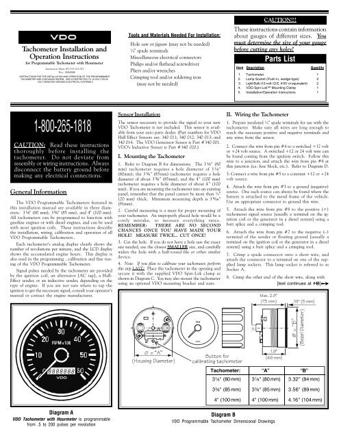
Diagram D Proper Wiring of the VDO Quartz Clock Diagram E Wiring examples of the VDO Engine Hour Meter Wiring the Quartz Clock: (Diagram D) 1. Run wires from the Quartz Clock location through the firewall to: a) The positive (+) terminal on the battery (after the fuse box, but before the ignition switch or any other switch.

Hobbs Hour Meter Wiring Diagram. Hour meter ("Hobbs") wiring Electrical Systems. They sent a PDF diagram, but basically it amounts to: 1. The meter is not polarity sensitive. 2. First, you must select an hour-meter model. Choose your model based on its ruggedness and apparent ease of installation. Having a waterproof hour meter is a.
Wiring the Gauge (Illustration A): 1. Route wires from the instrument to: (a) the battery (+) switched power after the fuse box or user supplied in-line fuse - 1A (b) the light switch after the fuse box or user supplied in-line fuse -1A (c) a good, dedicated ground location. 2. Connect the harness according to the following wiring Matrix: Pin ...
Digital Tach/Maintenance Hour Meter. # 706. Download. LCD Counters & Meters: T56F. LCD Vibration Activated Hour Meter With Magnet Mounting. # 705. Download. LCD Counters & Meters: PT30. LCD Panel Display.

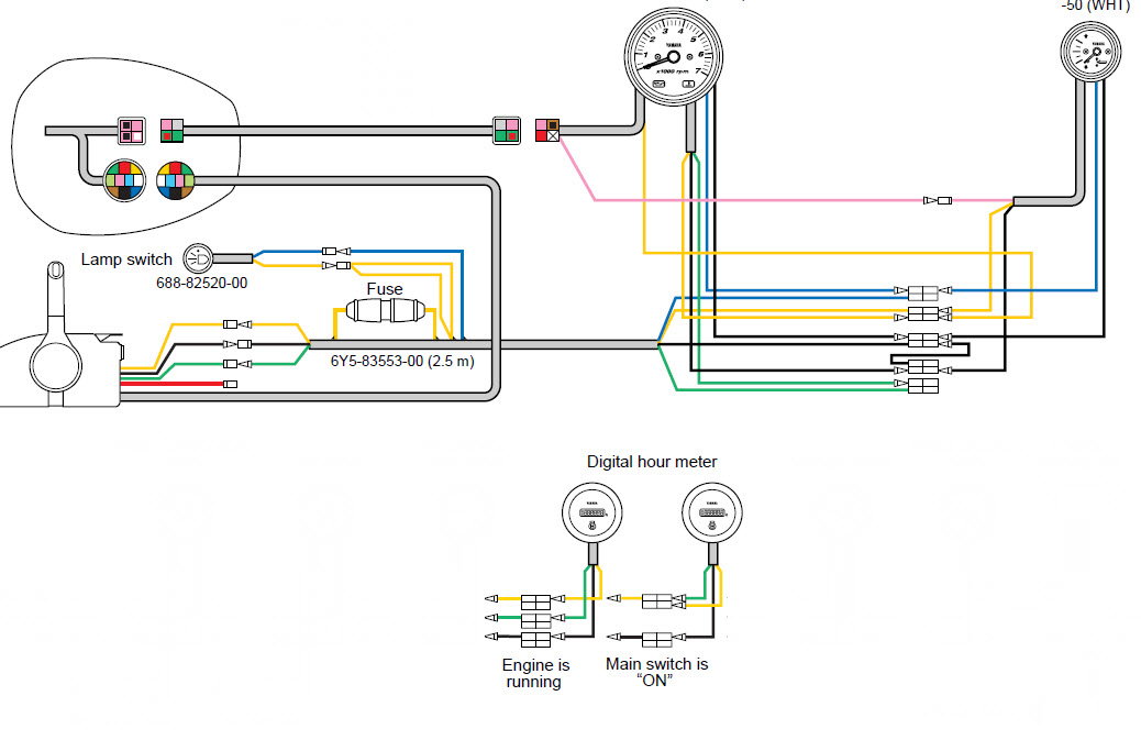
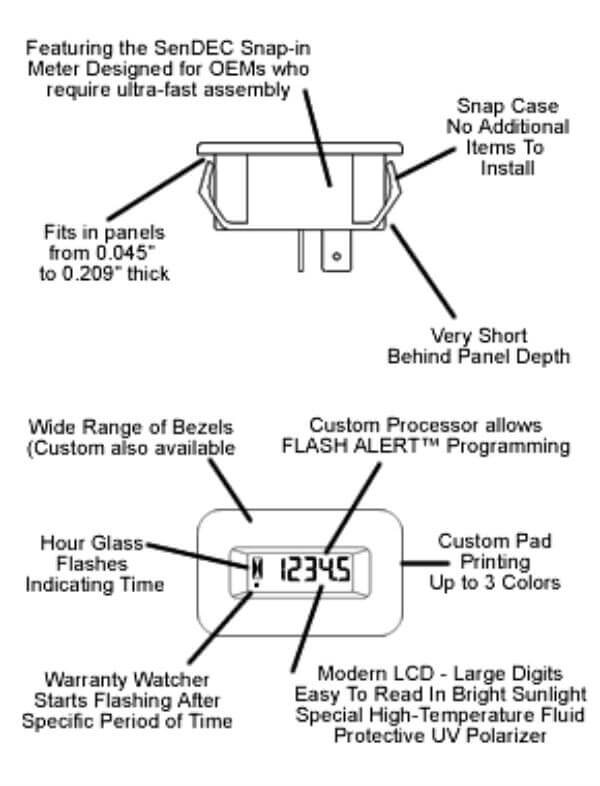
Unpack and attach the unit to a location where it can be easily read. Uncoil the shielded wire and wrap around 5 turns around the engine's spark plug wire. No ground wire is required. The LCD will display the accumulated hours on the hour meter and a HOURS icon. Press and hold the S1 button for 4 seconds.

An hour meter is a clock that requires switdched 12 volts and ground so it will run as long as the key is on -- engine running or not. But the question is -- why do you leave the key on. You cannot hook it to the coil because that is a pulsed signal. You cannot hook it to the tach as the "S" terminal is also pulsed and besides, it is nowhere ...

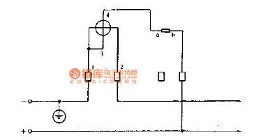
DIAGRAM SECTIDII 37-225 WIRING DIAGRAMS FOR WATTHOUR METERS (Rear View)-(Continued) II H• 8 A H G 81 AI D1 Cl J 5# 1392 631 l ti J I H G 0 c 8 A R5 C2 Cl2 R6 R4 Cl Gil R5 s'* 1392 636 iii( II HI 01 iftil Cl 81 AI To R6 C3 Cl3 R4 Alarm Fig. 22-Wiring Diagram R-3 Varhour
enough to reach the hour meter. 6. connect the third length of 18-gauge wire to a vehicle circuit where the wire will receive power only when the engine is running. this wire should also be long enough to reach the hour meter. 7. place recept acle insulators on each of the three 18-gauge wires (meter side), strip wire insula-

Induction wire length: 1500MM / 4.9 feet. BACKLIGHT TOTAL TIME Product Installation Tach/Maintenance/Hour Meter Wiring Diagram Specifications Features Programmable Backlight:ON/OFF/AUTO. 8 Programmable Firing Patterns. Programmable Maintenance Interval Timer (0~200 Hours). Programmable RPM alert. Max RPM Recall.
Hobbs hour meter wiring diagram. Run wires from the quartz clock location through the firewall to. That picture hobbs hour meter wiring diagram lovely garmin portable gps previously mentioned will be classed usingput up through mide in 2019 09 07 012536. You cannot hook it to the coil because that is a pulsed signal.
Hobbs Hour Meter Wiring Diagram - wiring diagram is a simplified satisfactory pictorial representation of an electrical circuit. It shows the components of the circuit as simplified shapes, and the knack and signal associates between the devices. A wiring diagram usually gives suggestion virtually the relative point and treaty of devices and ...

Connect the hot wire (usually red) on the back of the hour meter to the run wire on the back of the ignition switch, using a Scotch lock wire connector. Attach the ground wire (usually black) on the back of the meter to the boat's grounding system. Do this by connecting the wire to another ground wire with a Scotch lock, or connecting it to a ...

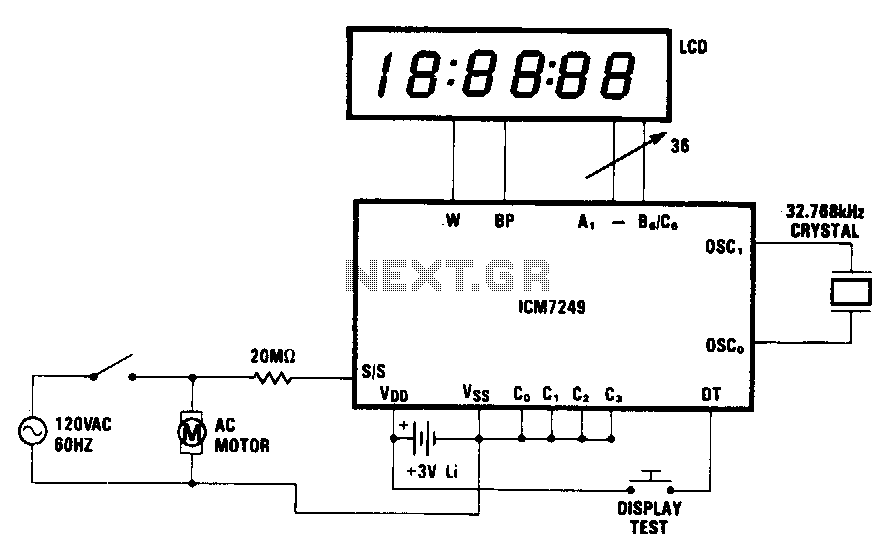
That will work, as long as the hour meter is a 220V rated unit.If the meter is 120V,connect 1 leg to a neutral on the compressor or if no neutral,connect it to ground.The other leg will still conect to a motor side terminal on the pressure switch.I know it's not "code" to hook up to ground to power the meter,but in this case,as long as the compressor is grounded,the current is so small through ...


/photo/2021/10/09/untitled-1jpg-20211009081923.jpg)


0 Response to "37 hour meter wiring diagram"
Post a Comment