40 isolation relay wiring diagram
Answer: In isolated mode the relay is completely electrically isolated from the control side. Large voltage spikes, shorts, etc. will not affect your controller. Therefore you need two separate voltage sources. One is for the relay side. This is put in the terminals closest to the edge. Use the t... A typical utility customer interface is shown in the FIGURE 1: Wiring Diagram. E. lectrical . The Latching Isolation Relay modules are designed utilizing mercury-wetted relays to provide the required equipment isolation. The K, Y, & Z inputs are connected through LED’s, which provide an indication of connectivity ...
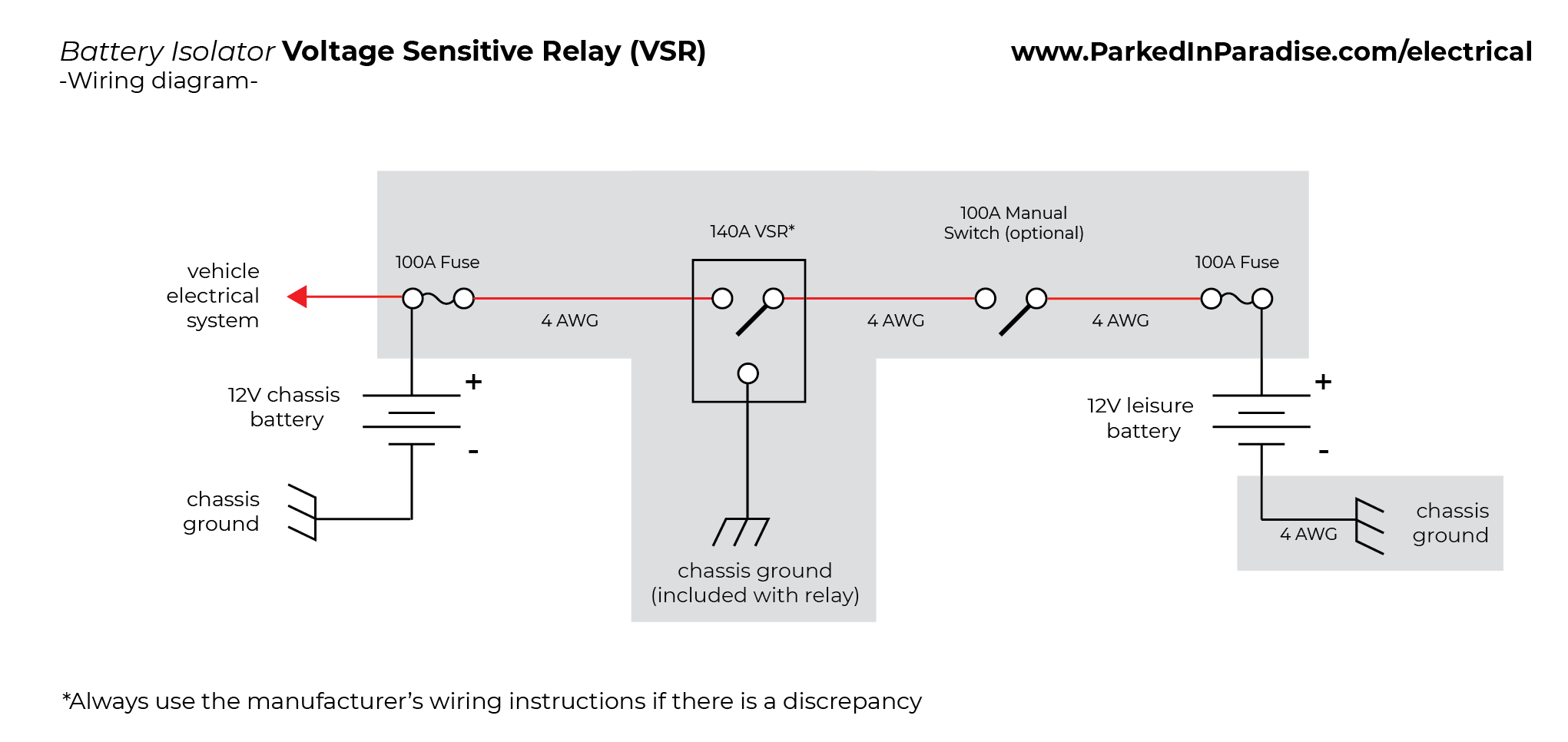
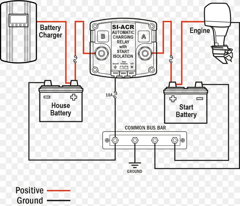
Learn how to wire your battery isolator (relay) so you can have two batteries in one vehicle. Topic: Car Audio Wiring Below is a diagram that shows the process. Next we will look at This particular model is the Stinger SR or SGP CS STYLE 4 POST BATTERY ISOLATOR. $ Part Number: S Use SGP35 or SGP32 Relay/Isolators for universal applications.
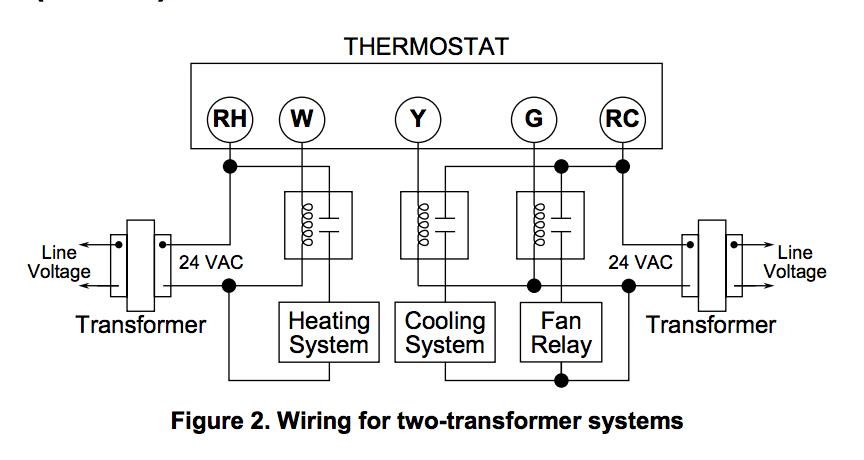
Isolation relay wiring diagram
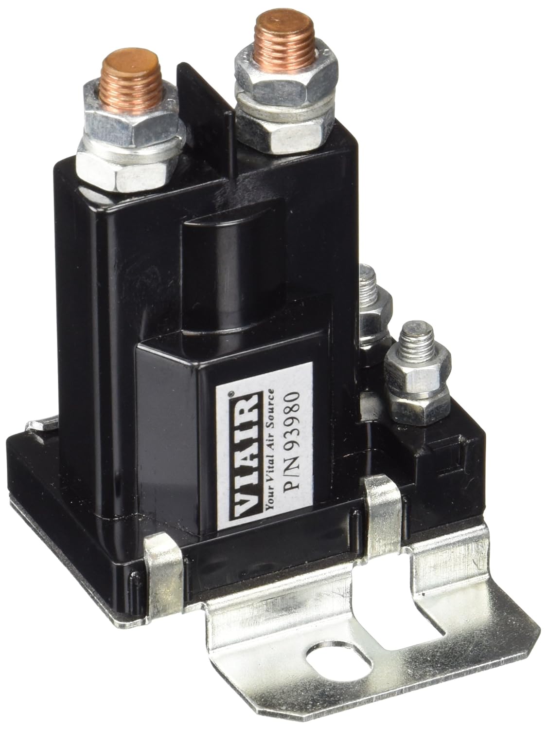
Wiring Diagram Wiring the relay: 1. The black wire coiled inside the relay needs terminated to a good ground location using the included blue crimp connector. This wire is simply used as a ground for activating the relay. 2. One terminal on the relay should be connected to the positive terminal of the primary starting battery using 6ga red wire. If the boiler utilizes dry-contact T & T terminals then an isolation relay is needed to have the ecobee3 interface with the boiler control. Below is a diagram ... This one shows how to wire the isolation relay sometimes used with oil furnaces. This video is part of the heating and cooling series of training videos mad...
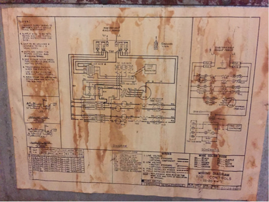
Isolation relay wiring diagram. Battery Isolator Relay Wiring Diagram Wiring Diagram Manual. Save Image [DIAGRAM] Woodward Solenoid Wiring Diagram FULL Version HD . Save Image. Keyline 12V 140 Amp Dual Battery Isolator The Van Mart. Save Image. Isolation relay question Electrical Toyota Motorhome . Isolation Relay Control Switch Wiring Furnace / Control Relay Isolation ... is to identify the furnace brand and model, then pick up the wiring diagram. Part of our wiring diagram and cyberbanking alternation apparent actuality on this channel. The accurate electromechanical relay is apparently the best broadly acclimated basic in automotive history and broadly acclimated to day.. 55 New Battery isolator Relay Wiring Diagram.Collection Of Automatic Charging Relay Wiring Diagram Download. Honeywell L4064B bination Fan and Limit Control: How to. • Single-line diagram (meter and relay single line or one line diagram) Shows the overall scheme and connections and interactions between equipment and relay system components but in a simplified manner. For example, it uses a single line to represent three phases (hence the name “single line”).
ISOLATION RELAY - 24V. USER'S GUIDE. 1 Description / Wiring. 75.5496.00 EN 20081217. Page 1 of 1. 2 Precautions. ❑ Shut off all power before attempting any ...1 page When installing a Butterfly panel at a building without an acccess control system, the butterfly needs to be wired directly to an electric lock.1 page This answer is not useful. Show activity on this post. You actually happen to have the relay oriented in your photo the same way the relay in the diagram is oriented. W1 to terminal 1. C to terminal 3. Boiler T&T wires to 2 and 4. Share. Improve this answer. Follow this answer to receive notifications. Putting a switch (or a jumper) between R & G will pull in the relay and operatet the boiler. R & G need relay contacts to work. The fix is to add a 24 volt relay with the coil pulled by wire 2 & 3 from the zone valves. Wire NO contacts from this new relay to R & G. Use a Honeywell R8225A1017 or a RIB relay.
IR882 Isolation Relay Module. Note: All terminals on the IR882 are Class 2. IR882 Wiring Schematics. Thermostat. Thermostat. Zone 2. Zone 1. Thermostat.4 pages And here is the wiring diagram for the relay: Can someone tell me how the ecobee diagram translates to the relay diagram? Which numbered terminals are going to ... 17 Dec 2008 — Always check placement of all wiring before powering up to insure that moving parts will not catch any wires and cause damage to equipment. ❑ ...1 page This one shows how to wire the isolation relay sometimes used with oil furnaces. This video is part of the heating and cooling series of training videos mad...
If the boiler utilizes dry-contact T & T terminals then an isolation relay is needed to have the ecobee3 interface with the boiler control. Below is a diagram ...
Wiring Diagram Wiring the relay: 1. The black wire coiled inside the relay needs terminated to a good ground location using the included blue crimp connector. This wire is simply used as a ground for activating the relay. 2. One terminal on the relay should be connected to the positive terminal of the primary starting battery using 6ga red wire.

860-880 North Lake Shore Drive, Electrical Riser Diagram (11/28/1949) // Ludwig Mies van der Rohe (American, born Germany, 1886–1969) Associate Architect: Holsman, Holsman, Klekamp and Taylor (American, 20th century) Associate Architect: Pace Associates (American, 20th century) Structural Engineer: Frank J. Kornacker (American, active 1940s–1950s)
Honeywell L4064B Combination Fan and Limit Control: How to Set the Temperatures and Limits on the Furnace Fan Limit Switch Control












0 Response to "40 isolation relay wiring diagram"
Post a Comment