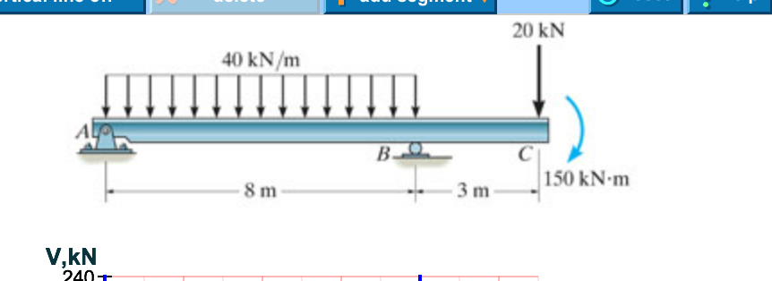
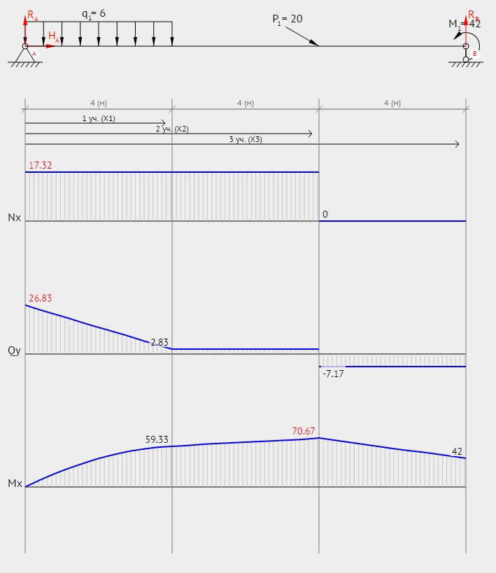
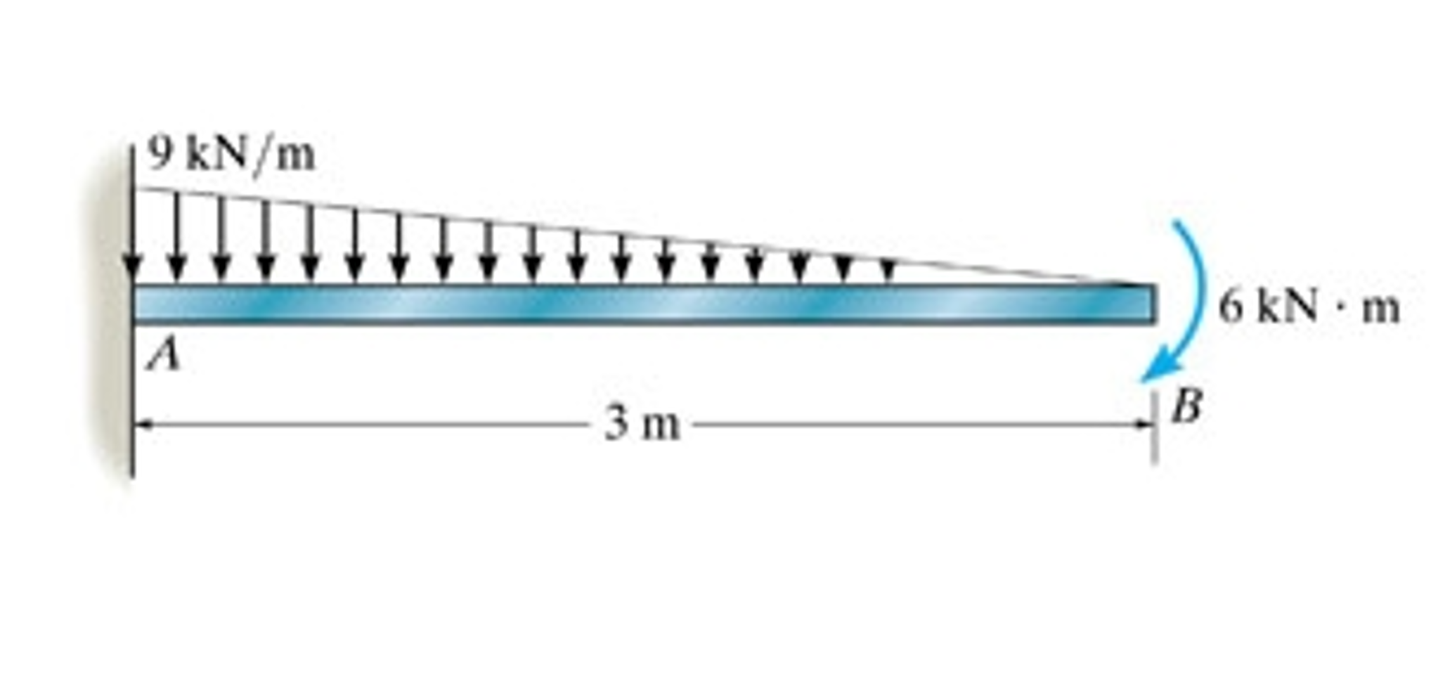
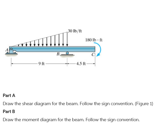
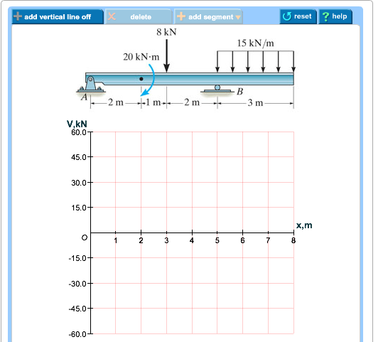
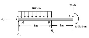
40 draw the shear diagram for the beam.
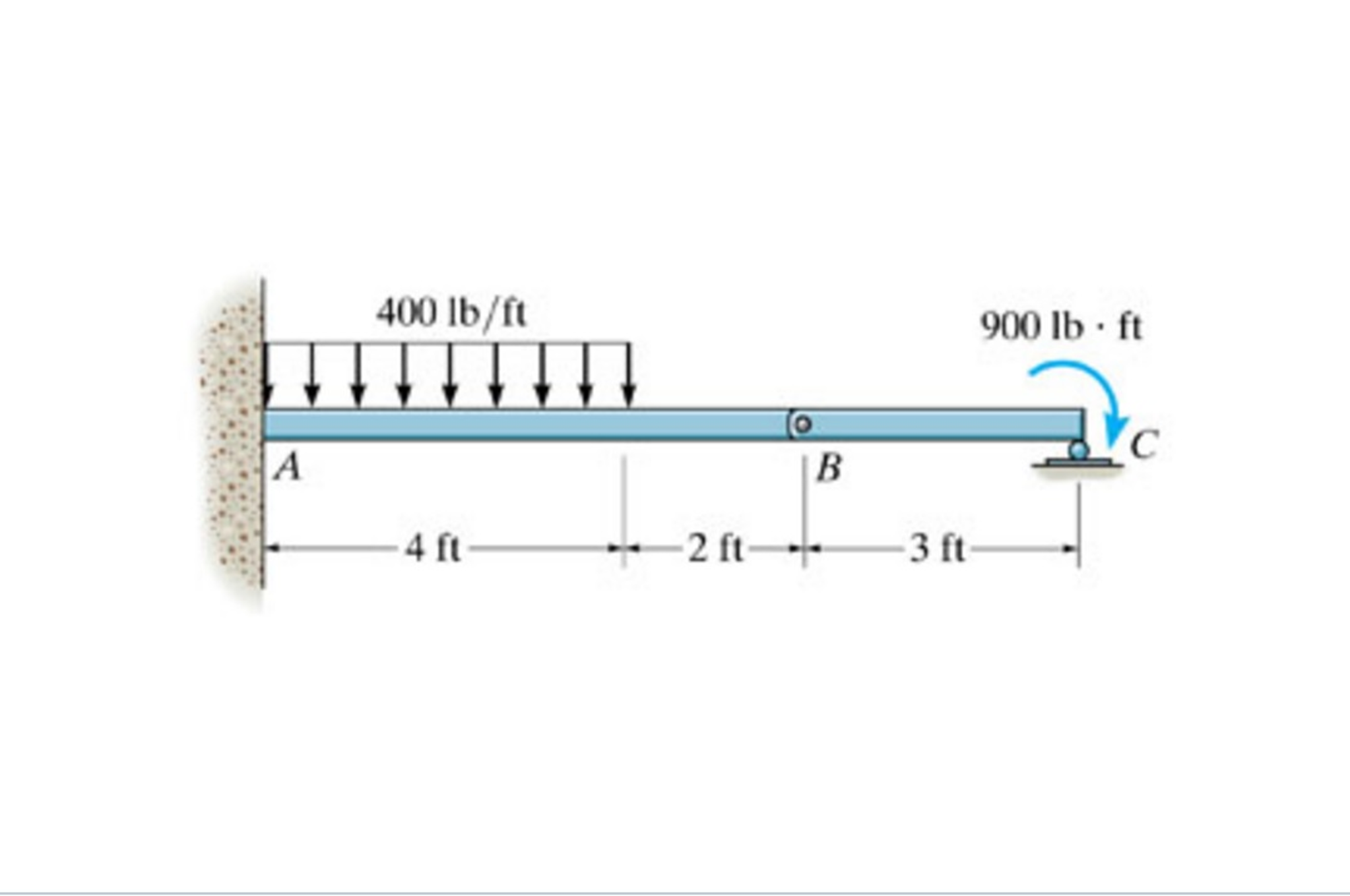
(Figure 1) Part B Draw the moment diagram for the beam. Follow the sign convention. This problem has been solved! See the answer ... Find the reactions and draw the Shear Force and Bending Moment Diagrams of the beam. ForceMethod Page 5 . Example: Frames ForceMethod Page 6 . ForceMethod Page 7 . Force Method of Analysis for (Indeterminate) Trusses ForceMethod Page 8 . ForceMethod Page 9 . Force Method of Analysis for (Inderminate) Composite Structures ForceMethod Page 10 . Part 1 Part 2 ForceMethod Page 11 . …
Draw the moment diagram for the beam. add vertical line off V(lb 1,000 750 500 250 250 -500 750 1,000. Show transcribed image text. Expert Answer.
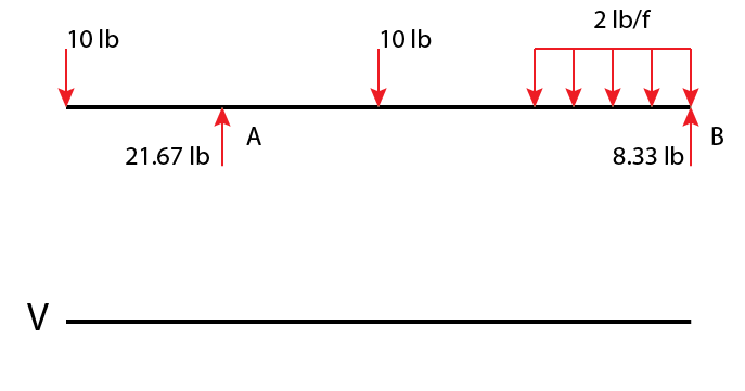
Draw the shear diagram for the beam.
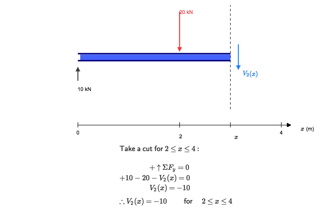
04.09.2017 · Shear force between any two vertical loads will be constant. And hence the shear force between the two vertical loads will be horizontal. The bending moment at the two ends of the simply supported beam and at the free end of a cantilever will be zero. Shear force and Bending moment Diagram for a Cantilever beam with a Point load at the free end Transcribed image text: Problem 7.70 Draw the shear diagram for the beam. Follow the sign convention. (Figure 1) Click on "add vertical line off" to add ... Shear and bending moment diagrams depict the variation of these quantities along the length of the member. Proceeding from one end of the member to the other, sections are passed. After each successive change in loading along the length of the member, a FBD (Free Body Diagram) is drawn to determine the equations express-ing the shear and ...
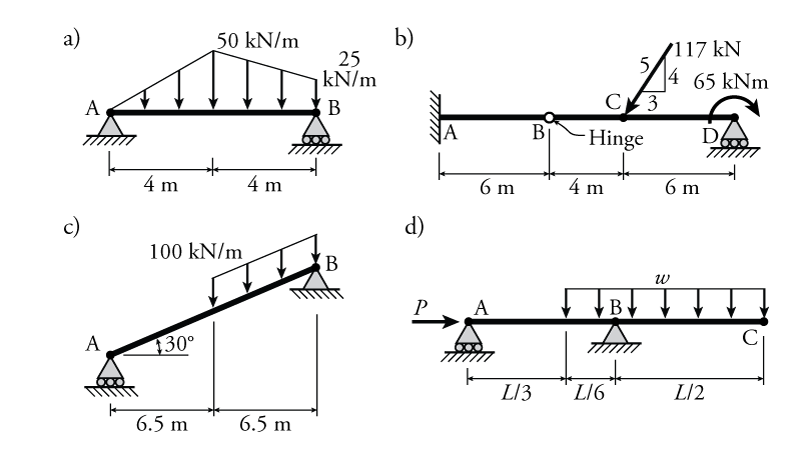
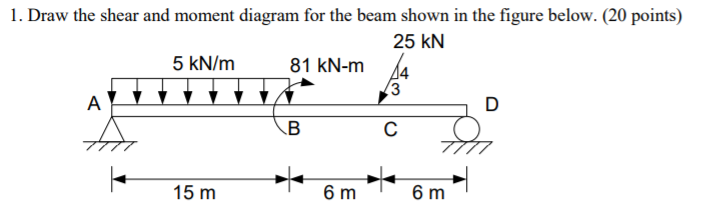
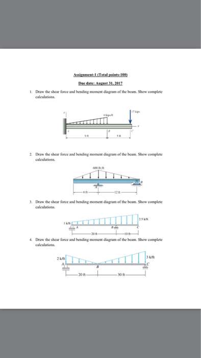
Draw the shear diagram for the beam.. Transcribed image text: Problem 7.53 Part A Draw the shear diagram for the beam Click on "add discontinuity" to add discontinuity lines. 05.03.2021 · Fig. P9.1. Simply supported beam. 9.2 Draw the influence lines for the reaction at A and B and the shear and the bending moment at point C of the beam with overhanging ends, as shown in Figure P9.2. Fig. P9.2. Beam with overhang. 9.3 Draw the influence line for the reactions at the support of the cantilever beam shown in Figure P9.3. Fig. P9.3 ... Shear and Moment Diagrams Consider a simple beam shown of length L that carries a uniform load of w (N/m) throughout its length and is held in equilibrium by reactions R1 and R2. Assume that the beam is cut at point C a distance of x from he left support and the portion of the beam to the right of C be removed. The portion removed must then be replaced by vertical shearing Problem 10: Bending Moment and Shear force A beam with a hinge is loaded as above. Draw the shear force and bending moment diagram. Solution: Concept: A hinge can transfer axial force and shear force but not bending moment. So, bending moment at the hinge location is zero. Also, without the hinge, the system is statically indeterminate (to a ...
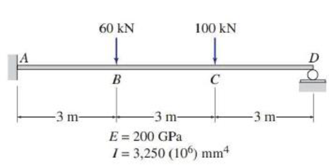
Transcribed image text: Problem 7.53 Part A Draw the shear diagram for the beam. Click on "add discontinuity" to add discontinuity lines. Question: 7.78 Draw the shear and moment diagram for the beam. This problem has been solved! See the answer ... 9.2 - Draw the shear force and bending moment diagram of this simply supported beam with a single applied point load at 1/3 span. Solution 9.3 - Draw the shear force and bending moment diagram of this simply supported beam with two applied point loads. Solution 9.4 - Draw the shear force and bending moment diagram of this simply supported beam with a uniformly distributed load acting on the ... 2.Draw the bending-moment diagram for the beam. Draw the shear diagram for the beam. Draw the ben. Show transcribed image text. Expert Answer.
Draw the shear diagram for the beam. Draw the moment diagram for the beam. PLEASE HELP! NOT SURE WHAT I AM DOING WRONG! Image for Draw the shear diagram for ... Shear and bending moment diagrams depict the variation of these quantities along the length of the member. Proceeding from one end of the member to the other, sections are passed. After each successive change in loading along the length of the member, a FBD (Free Body Diagram) is drawn to determine the equations express-ing the shear and ... Transcribed image text: Problem 7.70 Draw the shear diagram for the beam. Follow the sign convention. (Figure 1) Click on "add vertical line off" to add ... 04.09.2017 · Shear force between any two vertical loads will be constant. And hence the shear force between the two vertical loads will be horizontal. The bending moment at the two ends of the simply supported beam and at the free end of a cantilever will be zero. Shear force and Bending moment Diagram for a Cantilever beam with a Point load at the free end
Solved A Draw The Shear Diagram For The Beam Follow The Chegg Com

Drawing Bending Moment Diagrams Effectively Mechanicalbase
4 5 Practice Problems Learn About Structures
Shear Diagram Beam With 3 Supports Physics Forums
Solved Draw The Shear Diagram For The Beam Draw The Moment Chegg Com
Draw The Shear Diagram For The Beam
Determining The Shear Force And Bending Moment Equations Of Simply Supported Beam
4 4 Relation Among Distributed Load Shearing Force And Bending Moment Engineering Libretexts

For The Figure Below Draw The Shear And Moment Diagrams For The Beam Study Com

Draw The Shear And Moment Diagrams For The Cantilever Beam In Fig 6 15 A Holooly Com
Chapter 4 Internal Forces In Beams And Frames In Structural Analysis On Manifold Tupress

Part A Draw The Shear Diagram For The Beam Part B Draw The Moment Diagram For The Moment Study Com

Ultimate Guide To Shear Force And Bending Moment Diagrams Engineer4free The 1 Source For Free Engineering Tutorials
2
4 4 Relation Among Distributed Load Shearing Force And Bending Moment Engineering Libretexts
Solved Problem 7 75 Part A Draw The Shear Chegg Com
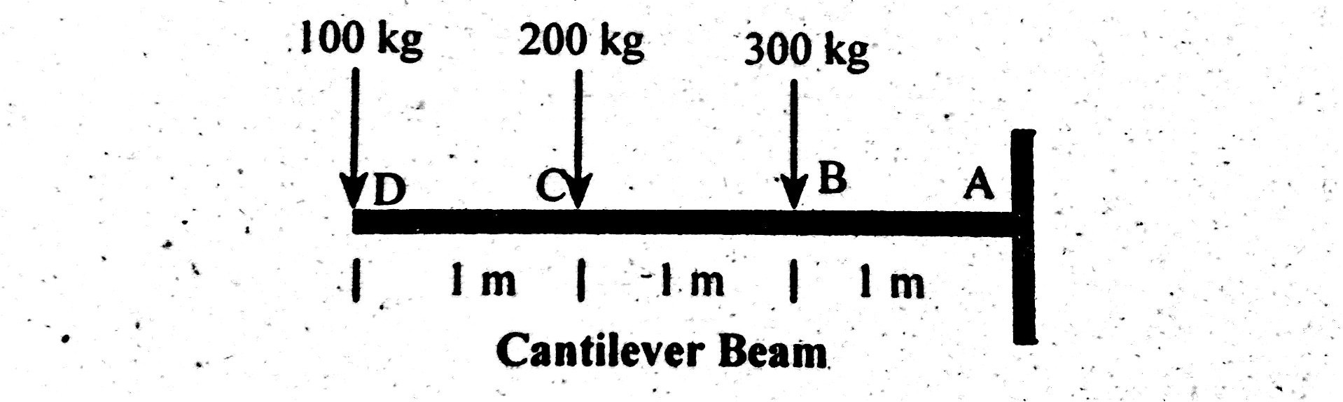
Shear Force Bending Moment Diagram Of Cantilever Beam Examples Engineering Intro
Draw The Shear
Solved 1 Draw Shear Force And Bending Moment Diagrams For The Beams Subjected To The Loadings Shown Below 2 A Calculate The Shear Forces And Be Course Hero
Solved Problem 7 90 Part A Draw The Shear Diagram For The Chegg Com
Draw The Shear Diagram For The Beam Studentshare

Drawing Shear And Moment Diagrams For Beam Youtube

329 6 1 Draw The Shear And Moment Diagrams For Aerostudents

Statics 7 71 Draw The Shear And Moment Diagram For The Beam Youtube
How To Draw Shear Diagrams Reviewcivilpe
Solved Draw The Shear Diagram For The Beam Draw The Moment Chegg Com

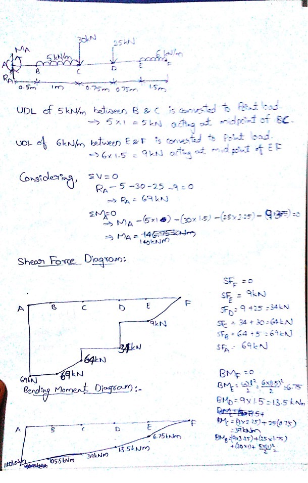
Draw The Shear And Moment Diagrams For The Beam With Calculation

Calculating Shear Force Diagrams Skyciv Engineering
Solved Structural Analysis Drawing Shear And Moment Dia
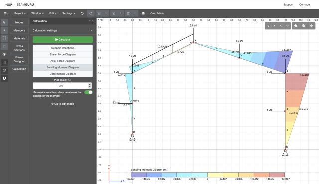
Beamguru Com Beam Calculator And Frame Truss Beam Calculator Online Draws Bending Moment Shear Force Axial Force
Solved The Compound Beam Is Fixed At A Pin Connected At B And Supported By A Roller At C Draw The Shear And Moment Diagrams For The Beam
Draw The Shear Diagram For The Beam Draw The Moment Diagram For The Beam Home Work Help Learn Cbse Forum
Calculating Shear Force Diagrams Skyciv Engineering
Solved Draw The Shear Force And Bending Moment Diagram Of The Beam Show 1 Answer Transtutors
Draw Shear Force Diagram And Bending Moment Diagram For Beam Shown In Figure 4 Nbsp

A Beam Is Shown In The Figure Below Part A Draw A Shear Diagram For The Beam Part B Draw The Moment Diagram For Th Homeworklib
1

Draw The Shear And Moment Diagrams For The Beam Docsity
Calculations For Shear Force And Bending Moment Diagram For Overhanging Beam

Draw The Shear And Moment Diagram For The Beam And Loading Shown Study Com
0 Response to "40 draw the shear diagram for the beam."
Post a Comment