39 nurse call systems wiring diagram
Appendix 4: Wiring Diagram for Nurse Call System. (UL 1069). 59. 12.0. Appendix 5: Device Installation Table. 60. 13.0. Warranty and Warning Information. The prerequisite for starting up the Gira nurse call system Plus ... Figure 3.23: Example of wiring diagram for connection of bus participants to ward bus ...
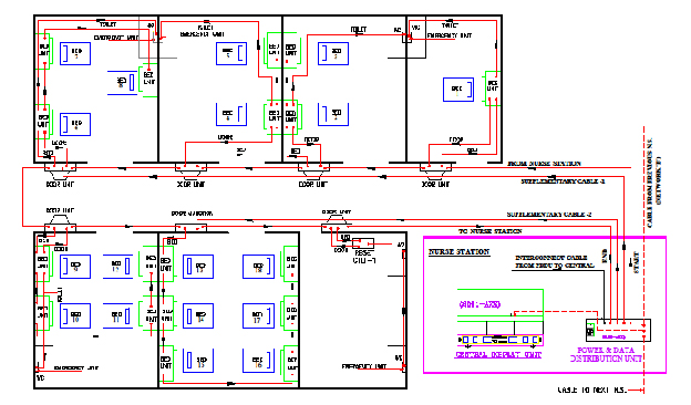
wires plus 1 0.2mm2 core per zone between panels. Sounders. Run 1 core plus 1 or 2 common cores to the nearest panel. Call Points. Run 1 signal wire per ...

Nurse call systems wiring diagram
NC9100 Auth Florence Nurse Call System Wiring Diagram. Jpeg Format. Wiring diagrams for the Visual Nurse Call System 4000 Series from Cornell Communications Emergency Call Systems. Plug in connector/cable assembly supplied with each station. Connect wires as shown in wiring diagrams. Page 19. IL600 NC205 Tek-DIGICARE® Manual ...
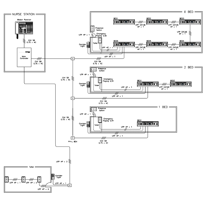
Nurse call systems wiring diagram. IMPULSE CALL UNIT. (MO3). RESET UNIT. (MO4). TV SOUND. B. R. K. R. K. 8 CORE COMMS. MICRO NURSECALL SYSTEMS. UB-4 NURSE CALL SYSTEM WIRING. The Tek-CARE® NC300™II Series Nurse Call System is designed for hospitals, nursing ... Figure 33 — LI386-series Dome/Zone Light Wiring Diagram . Find all the specifications and information you need for your Cornell nurse call or emergency communication system. Wiring Diagrams. 14. 2 Bed with bathroom. (With Emergency). 15. 4 Bed wiring. (Without Emergency). 16. Connector board wiring. 17. Impulse pull cord wiring.
Plug in connector/cable assembly supplied with each station. Connect wires as shown in wiring diagrams. Page 19. IL600 NC205 Tek-DIGICARE® Manual ... Wiring diagrams for the Visual Nurse Call System 4000 Series from Cornell Communications Emergency Call Systems. NC9100 Auth Florence Nurse Call System Wiring Diagram. Jpeg Format.

Pengertian Nurse Call Nursecallrumahsakit Com

Digital Call System Dcs Manualzz
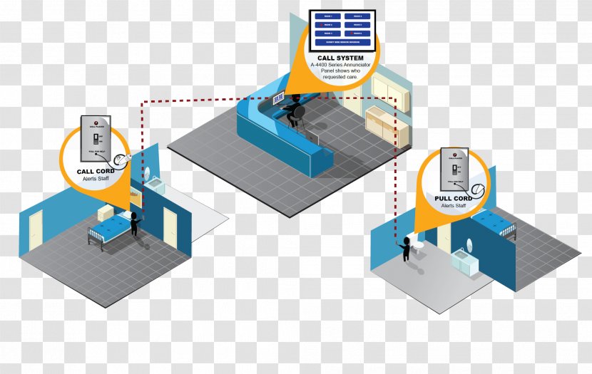
Nurse Call Button Nursing Care Hospital Home Diagram System Wiring Transparent Png
2

System Of A Call Of Personnel Zkr Stage Zkr Tm All Biz
2

Electrical Cable Wire Electrical Connector Wiring Diagram Nurse Call Button Bundles Electrical Wires Cable Cable Electrical Connector Png Pngwing

Nurse Call Installation Youtube

Tacera Hardware Installation And Cabling Guide1 Room Controller Interface Tacera Room Controller Tacera Nurse Call Pubhtml5
.jpg)
You Are Here Skip Navigation Links Home News News Transtel Announces Major Development In Health Care Communications Market Phone 1 561 747 4466 Fax 1 561 935 4734 E Mail Info Transtelcommunications Com Skip
2
Telereach
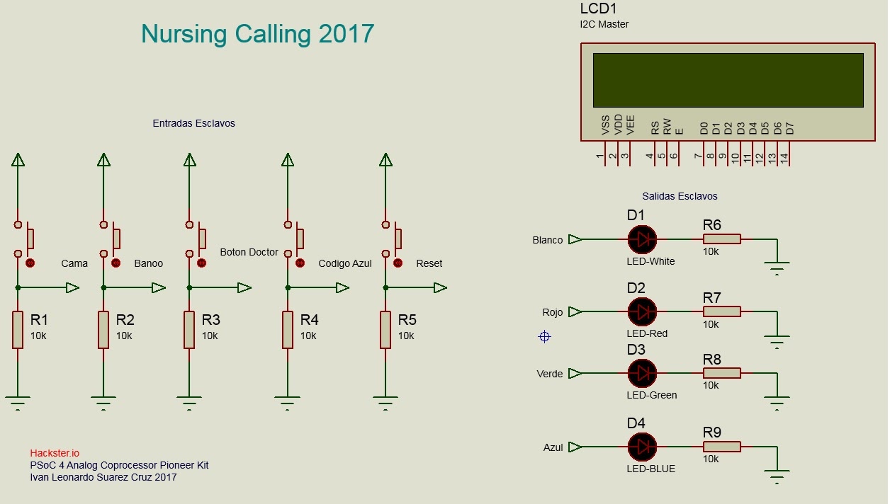
Nursing Call For Patient Care Hackster Io

The Nurse Call Solution For Hospitals

Commax Nurse Call Suricon

Sistem Elektronika Pada Rumah Sakit Sistem Nurse Call Aiphone

Nurse Call System Suricon

Jual Nurse Call System Untuk 10 Ruangan Kamar Rumah Sakit Klinik Kota Bandung Ipsoft Bandung Tokopedia

Commax Nurse Call Suricon
1

Emergency Nurse Call System News Eameday Medical Apparatus And Instruments Manufacturer

General Concept Of Nurse Call System 2 Download Scientific Diagram
2
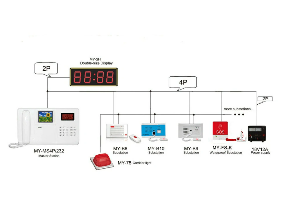
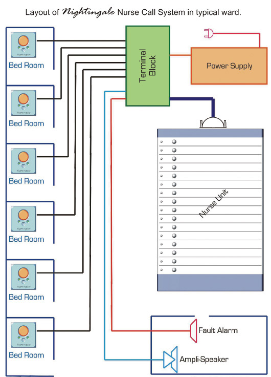
Meeyi Wired Nurse Intercom System

Image Result For Nurse Call System Wiring Diagram Call System Diagram Hospital Design
2
2

Pdf Rfid For Nurse Activity Monitoring In The Hospital S Nurse Call System With Internet Of Thing Iot Concept
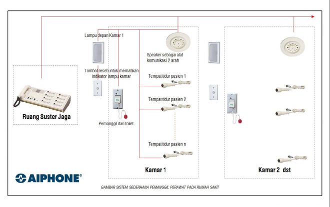
Aiphone Nurse Call Suricon
Wiring Diagrams Pdf S For Nurse Call Area Of Refuge Systems Cornell Communications Emergency Call Systems

Ip System Of A Call Zkr Versatile Zkr Tm All Biz

Soca S11 Nurse Call System Innovative Solution
Emergency Call System Installation Nurse Call Systems Installed Accurately Cornell Communications Emergency Call Systems
Dm Health Care

Medical Nurse Call System Installations Bed Emergency Buttons Micro Nurse Call System Nurse Emergency Alert Systems For Hospital Retirement Homes Installation Repairs
Wireless Nurse Call System With Software Management 20 Call Button Shopee Indonesia
Intercall 600 Installation Operation Manual Pdf Download Manualslib

Disrupting Nurse Call How Nurse Call Is Changing Medical Connectivity
Nurse Call System Medimaxkorea Co Ltd
0 Response to "39 nurse call systems wiring diagram"
Post a Comment