37 volvo v70 fuse box diagram
Fuse Box Diagram, Volvo. by Pad Rust. Volvo S70 In The Cargo Area Fuse Box/Block Circuit Breaker Diagram. POS. RELAY OPERATION. RMA1. Relay, 15 feed, rear accessories 2/ 52. RMA3. Relay, heated rear windows 2/ 82. Volvo XC70 (2006) - fuse box diagram. In this article you will find a description of fuses and relays Volvo, with photos of block diagrams and their locations. Highlighted the cigarette lighter fuse (as the most popular thing people look for). Get tips on blown fuses, replacing a fuse, and more.
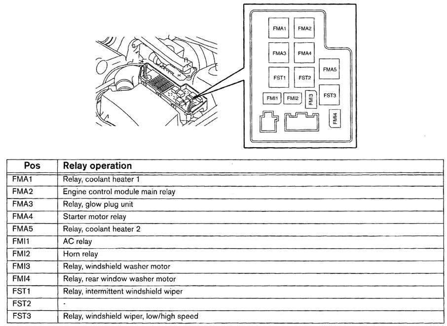
Relay Locations.. See the illustrations below left and middle to identify relays in 740/940 cars.Caution: relay locations vary by model, year, and market: to determine differences, use an OEM wiring diagram book.To access relays, remove the ashtray (push the spring clip at the top) and fuse panel cover (push the plastic snap at the bottom).
Volvo v70 fuse box diagram
Volvo V70 XC 2000 Inside Dash Fuse Box/Block Circuit Breaker Diagram. No. Fuse Function. Amps. 23. Light Switch Module (LSM), Data Link Connector, Climate Control Module (CCM) 5A. 24. Extended X Feed Via Relay, Climate Control Module (CCM), Driver Information Module (DIM), Power Driver Seat, Geartronic, Shift Lock, Cobustion Preheater Module ... See more on our website: https://fuse-box.info/volvo/volvo-v70-xc70-2008-2010-fuses-and-relaysFuse box diagram (location and assignment of electrical fuses a... Fuse box diagram (location and assignment of electrical fuses and relays) for Volvo V70/XC70 (2011, 2012, 2013, 2014, 2015, 2016).
Volvo v70 fuse box diagram. Volvo 850, S70, V70, XC70, C70 fuses and fuse box location photos, for reference. Post categories. In Volvo 850, Volvo C70, Volvo Electrical & Battery, Volvo Repair Documentation, Volvo S70 & V70 1998-2000, Volvo V70 R 1998-2000, Volvo XC70 & V70XC. See more on our website: https://fuse-box.info/volvo/volvo-v70-xc70-2011-2016-fuses-and-relaysFuse box diagram (location and assignment of electrical fuses a... Volvo Car Pdf Manual Wiring Diagram Fault Codes Dtc. Volvo v70 xc70 v70r xc90 2004 headlights r system auxiliary driving lamps wiring diagram pdf horn 2005 interior lights ewd 2011a electronic exterior 2006 2010 usa car electrical connections manual randomly turn on 2000 to 2007 fuses ii fuse box diy 1998 fuel 5cyl trunk radio stereo audio tailgate wire harness repair automatic gear shift 2003 ... Fuse box diagram (location and assignment of electrical fuses) for Volvo C70 (2006, 2007, 2008, 2009, 2010, 2011, 2012, 2013).
All Volvo V70 II info & diagrams provided on this site are provided for general information purpose only. Actual Volvo V70 II (2000-2007) diagrams & schemes (fuse box diagrams & layouts, location diagrams, wiring diagrams etc.) may vary depend on the model version. Volvo V70 mk1 (First Generation; 1998) - fuse box diagram Year of production: 1998 Relay/Main fuse box Relays Position Function 15 System relay 16 Air pump relay 17 Starter motor 18 Air conditioning Fuses in Relay/Main fuse box (main system fuses) Position Function Ampere rating [A] 1 Electric cooling fan 60 2 Fuses in Supplementary … The compact station wagon Volvo V50 was produced from 2004 to 2012. In this article, you will find fuse box diagrams of Volvo V50 2004, 2005, 2006, 2007, 2008, 2009 ... Volvo XC70 5cyl 2001 Fuse Panel/Board - Fuse Symbol Map Related diagrams: Volvo C30 Hatchback 2014 Fuse Box/Block Circuit Breaker Diagram Volvo V-40 2002 Passenger Fuse Box/Block Circuit Breaker Diagram Volvo V70 1999 Compartment Fuse Box/Block Circuit Breaker Diagram Volvo S.60 2012 Engine Fuse Box/Block Circuit Breaker Diagram
In this article, we consider the third-generation Volvo V70 / Volvo XC70 before a facelift, produced from 2007 to 2010. Here you will find fuse box diagrams of Volvo V70 2008, 2009 and 2010, get information about the location of the fuse panels inside the car, and learn about the assignment of each fuse (fuse layout) and relay. Volvo XC70 (2014) - fuse box diagram. Year of production: 2014. Fuses - engine compartment. A - Engine compartment, upper. B - Engine compartment, front Volvo V70 5cyl Trunk 2004 Fuse Box/Block Circuit Breaker Diagram. No. Fuse Function. Amps. 23. Light Switch Module (LSM), Data Link Connector, Climate Control Module (CCM) 5A. 24. Extended X Feed Via Relay, Climate Control Module (CCM), Driver Information Module (DIM), Power Driver Seat, Geartronic, Shift Lock, Cobustion Preheater Module (CPM ... Volvo Ewd 2011a Electronic Wiring Diagrams. Volvo s70 v70 c70 1999 electrical xc wiring diagram compartment fuse box all diagrams for glt instrument cer s80 radio 10 tp3941202 v70r xc70 xc90 electronic diy 1998 fuel system p80 dolby stereo amplifier service manual pdf auxiliary driving lamps interior lights ewd 2011a o i have no voltage from ignition to starter motors repair manuals car audio ...
cooling fan relay location - Volvo Owners Club Forum
Fuse Layout Volvo V70 / XC70 2008-2010. Fuse box location. 1) Under the glovebox. It is located under the lining.

Volvo V70 Wiring Diagram 2004 - Wiring Diagram
The video above shows how to replace blown fuses in the interior fuse box of your 2001 Volvo V70 in addition to the fuse panel diagram location. Electrical components such as your map light, radio, heated seats, high beams, power windows all have fuses and if they suddenly stop working, chances are you have a fuse that has blown out.
silver and gold coin collection
S70 T5 N/A GLT GLT Volvo V70 Wiring Diagram ~ here you are at our site, this is images about volvo v70 wiring diagram posted by Brenda Botha in category on Nov 22, You can also find other images like wiring diagram, parts diagram, replacement parts, electrical diagram, repair manuals, engine diagram, engine scheme, wiring harness, fuse box ...

magic fuel pump - Turbobricks Forums
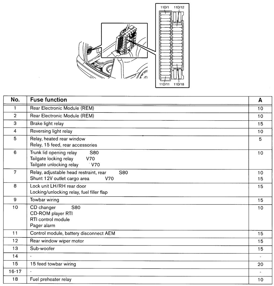
The fuses in the cargo area are located behind the panel on the driver's side of the cargo compartment. Volvo XC70 - fuse box -. tunk. Position. Function. Ampere rating [A] 1. Backup lights. 10.
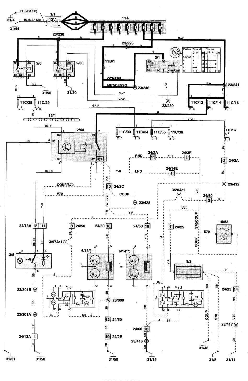
Volvo V70 (2001) - wiring diagrams - fuse panel ...
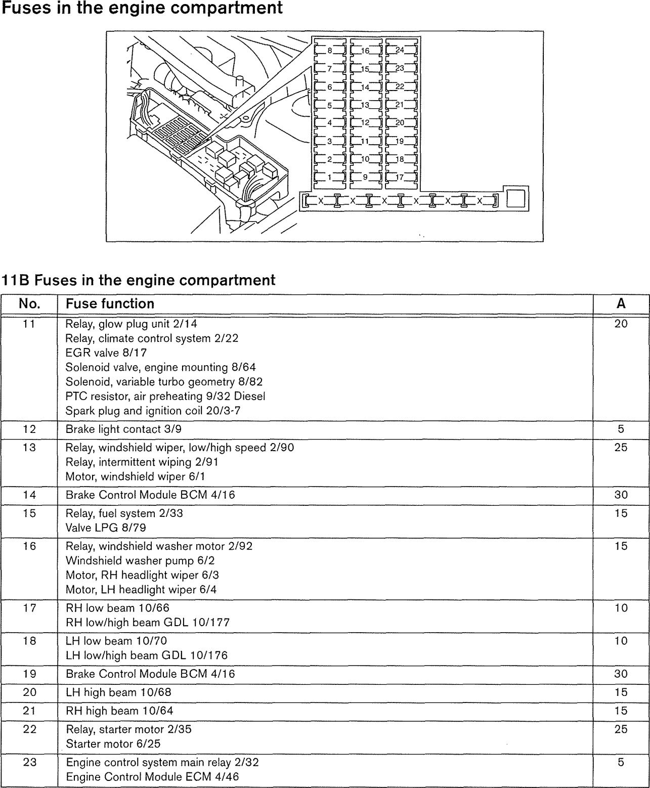
by Pad Rust. Volvo V70 Engine 1997 Fuse Box/Block Circuit Breaker Diagram. Symbol. Description. ENGINE COMPARTMENT RELAY/FUSE BOX. 1. Fuel System Main Relay. 2. Starter Motor Relay.

Fuse Box Volvo V70 2001 - Wiring Diagram
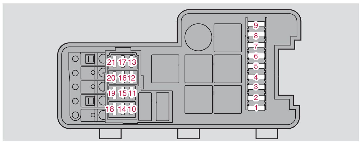
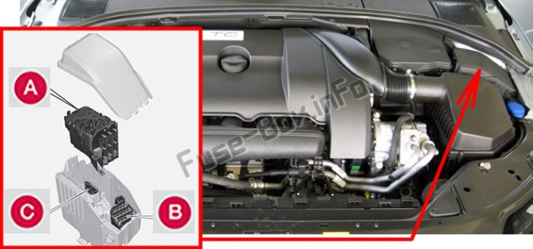
The 2005 to 2007 Volvo V70 / XC70 have four fuse boxes: A - Relays/ fuse box in the engine compartment. B - Fuse box in the passenger compartment, on the edge of the dashboard. C - Fuse box in the passenger compartment, behind plastic cover. D - Relays/ fuse box in the trunk.
green plants near gray concrete bridge during daytime
All Volvo S70 & V70 I info & diagrams provided on this site are provided for general information purpose only. Actual Volvo S70 & V70 I (1996-2000) diagrams & schemes (fuse box diagrams & layouts, location diagrams, wiring diagrams etc.) may vary depend on the model version.
green coated wire on car
Volvo XC70 (2009) - fuse box diagram. Year of production: 2009. Fuses - engine compartment. A - Engine compartment, upper. B - Engine compartment, front

Volvo V70 (2002) - wiring diagrams - fuse panel - CARKNOWLEDGE
Volvo V70 - wiring diagram - fuse panel (part 7) Volvo V70 - wiring diagram - fuse panel (part 8) Volvo V70 - wiring diagram - fuse panel (part 9) WARNING: Terminal and harness assignments for individual connectors will vary depending on vehicle equipment level, model, and market. Electrical Distribution. Wiring diagrams.

The Changeling (c. 1780) // Attributed to Henry Fuseli Swiss, active in England, 1741-1825
1998 Volvo S90 Fuse Box Location ️ 1997 Volvo 850 Fuse Box Location Volvo Central Electronic Module CEM Removal Procedure for XC90, XC70, V70, S60, S80 1999 - 2004
Volvo V60 (2011-2018) Fuse Box Diagrams - YouTube
Fuse box diagram (location and assignment of electrical fuses and relays) for Volvo V90 (also Cross Country and Twin-engine) (2017, 2018, 2019…) Volvo XC40 (2018-2019..)…>>. Fuse box diagram (location and assignment of electrical fuses and relays) for Volvo XC40 (2018, 2019…) Volvo XC60 (2009-2012)…>>.
Volvo V70 5cyl Trunk 2004 Fuse Box/Block Circuit Breaker ...
Fuse box diagram (location and assignment of electrical fuses and relays) for Volvo V70/XC70 (2011, 2012, 2013, 2014, 2015, 2016).
Volvo S60 mk1 (First Generation; 2006) - fuse box diagram ...
See more on our website: https://fuse-box.info/volvo/volvo-v70-xc70-2008-2010-fuses-and-relaysFuse box diagram (location and assignment of electrical fuses a...

Perseus Starting from the Cave of the Gorgons (c. 1816) // Attributed to Henry Fuseli Swiss, active in England, 1741-1825
Volvo V70 XC 2000 Inside Dash Fuse Box/Block Circuit Breaker Diagram. No. Fuse Function. Amps. 23. Light Switch Module (LSM), Data Link Connector, Climate Control Module (CCM) 5A. 24. Extended X Feed Via Relay, Climate Control Module (CCM), Driver Information Module (DIM), Power Driver Seat, Geartronic, Shift Lock, Cobustion Preheater Module ...
VOLVO V70 II (SW) Fuse Box 28017881 30728273 30728512 5452807
Volvo V70 mk1 (First Generation; 1998) - fuse box diagram - Auto Genius

Volvo S40 1999 Fuse Box - Complete Wiring Schemas

Mother and Her Family in the Country (1806/07) // Henry Fuseli Swiss, active in England, 1741-1825
Fuse Box Diagram Volvo V70/XC70 (2011-2016)
VOLVO V70 II (SW) Fuse Box 28017881 30728273 30728512 5452807

purple flower field during daytime
2008-2017 Volvo XC60 Fuse Box Diagram » Fuse Diagram
Volvo V70 (2002) - wiring diagrams - fuse panel - CARKNOWLEDGE

Volvo Xc70 Fuse Box - Complete Wiring Schemas

Fuse Box Volvo V70 2001 - Wiring Diagram
2001 Volvo V70 XC 5cyl Fuse Box Diagram – Auto Fuse Box ...
Fuse for fuel pump blowing in 2006 volvo xc70 where is fuel - Fixya

The Discovery (recto), Two Sketches of Standing Male Figures (verso) (1767/69) // Henry Fuseli Swiss, active in England, 1741-1825
Fuse Box Diagram Volvo S60 (2001-2009)
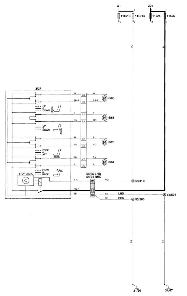
Volvo V70 (2001 - 2002) - wiring diagrams - power seat ...
Volvo V70 (2001) - wiring diagrams - fuse panel ...
assorted iPhone boxes on white surface
I have a constant ticking sound coming from the door of my 2002 Volvo s60. The lock does not open and the electric side

Sketch for "Oath on the Rütli," Female Figure (verso) (1779/81; 1785/90 (verso)) // Henry Fuseli Swiss, active in England, 1741-1825
Volvo 850 fuses & circuit breakers service manual | Volvotips
2000 Volvo S70 Fuse Box Diagram - Cars Wiring Diagram Blog

Study for Inquisition, Illustration to Columbiad (c. 1806) // Henry Fuseli Swiss, active in England, 1741-1825
0 Response to "37 volvo v70 fuse box diagram"
Post a Comment