37 tin bismuth phase diagram
prism is a two-component temperature-composition phase diagram with Pb Triple Eutectic 3-Dimensional Depiction of Temperature-Composition Phase Diagram of Bismuth, Tin, and Lead at 1atm. The diagram has been simplified by omission of the regions of solid solubility. Each face of the triangular a eutectic. Civil Engineering questions and answers. QUESTION 30 Figure 3 shows the equilibrium phase diagram for the tin-bismuth binary alloy system What phases would be expected to be present in an alloy of composition 90 wt% Sn. 10 wt% BI held at 150°C? Assume equilibrium conditions apply. (1 mark) a) (B-Sn) b) (B-Sn) + L C) (B-Sn) + (BI) d) (BI) + L ...
If you look closely at the Tin-Bismuth phase diagram or the lead bismuth phase diagram small amounts of bismuth will just go into a solid solution in the tin phase or the lead phase. For example ...
Tin bismuth phase diagram
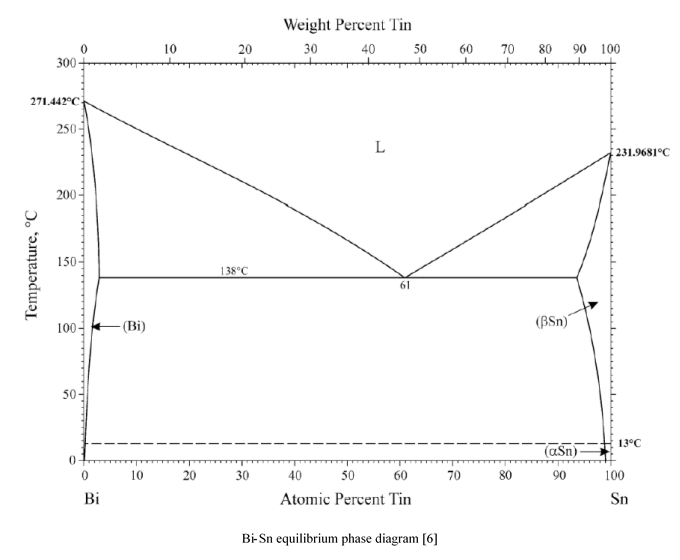
Phase Diagrams • Indicate phases as function of T, Co, and P. • For this course:-binary systems: just 2 components.-independent variables: T and Co (P = 1 atm is almost always used). • Phase Diagram for Cu-Ni system Adapted from Fig. 9.3(a), Callister 7e. (Fig. 9.3(a) is adapted from Phase Diagrams of Binary Nickel Alloys , P. Nash Status of the thermodynamic description: B.-J. Lee, C.-S. Oh and J.-H. Shim, J. Electron. Mater. 25 (1996) 983-991: Full thermodynamic assessment. Allen and Jesser [49] evaporated 99.99% Bi and Sn on amorphous C films to make alloys with 40 nm grains, and observed them via using in situ TEM. Fig. 7.7 shows one of their phase diagrams. The solid and dashed lines show the phase diagrams of conventional and nanoalloys, respectively. In each of the nanoalloy phase diagrams the solidus and liquidus fully move down; therefore the melting point ...
Tin bismuth phase diagram. An experiment can be performed to get a rough idea of a phase diagram by recording cooling curves for alloys of two metals, in various compositions. The alloy chosen for this example is bismuth-tin, both of which metals have low melting points, and so can be heated and cooled more quickly and easily in the lab. low enough temp. that the phase diagram shows nothing more is going on. - read the graph accordingly to determine the temperatures used for the phase diagram. - repeat with each alloy sample. ... Sample # Bismuth Tin Sample # Bismuth Tin 1 100 0 1 10 0 2 97.5 2.5 2 9.74 0.25093 3 95 5 3 9.5153 0.4999 4 90 10 4 9.039 1.0065 5 70 30 5 7.0023 2.9719 has been pre-tinned with a tin-lead or tin-bismuth alloy with a solder of a different composition may result in the formation of a low-melting higher-component eutectic. In this case, the multi-component phase diagram can be used to evaluate the possible effects resulting from such a contamination. Traditionally, phase diagrams are Sep 14, 2021 · Tin was recovered in metal from an industrial tin-bearing byproduct containing Na2SO4 by carbothermic reduction smelting, and the effects of basicity (Na2O/SiO2), temperature, and reaction time on the recovery of tin were studied. Na2SO4 was reduced by carbon and formed into sodium silicate slag (Na2O–SiO2) in the presence of SiO2. Tin content in slag decreased with the increase of Na2O/SiO2 ...
Principles. Solid-liquid phase diagrams are of great value in the technical study of alloys, ceramics and in the recovery of a salt by crystallization from a mixture of salts. The binary solid-liquid phase diagram in Figure 1 shows the stability of different phases as a function of temperature at a given pressure. A further phase transition to an orthorhombic Pnma structure occurs between 125 and 150 K. Kahmann et al. observed a transition from a cubic room-temperature phase to a tetragonal phase at around 255 K and a second tetragonal phase below 155 K instead of the orthorhombic structure reported by Schueller et al. The variability in the data ... According to phase diagram of tin-bismuth binary system [75] the eutectic alloy contains 39.0 at.% of tin included into two crystalline phases of bismuth and -tin ( Figure 18). The latter ... tin, which melts at 232oC. In low temperature soldering a number of alloying elements can be used to reduce tin's melting temperature. Ga, In, Bi, and Cd are effective in reducing the melting temperature of solder alloys, although Cd is not often considered due to its toxicity. Gallium-containing
As shown in the phase diagram Figure 1, at the eutectic composition, the tin-bismuth alloy melts at 139°C. In fact, the nanoparticles likely melt at a slightly lower temperature than this due to ... Tin Bismuth Phase Diagram - Titania Nanotube Stabilized Biocl Nanoparticles In Visible Light characterization of eutectic sn bi solder joints springer the sn bi phase diagram 9 indicates that the eutec tic characterization of eutectic sn bi solder joints 601 500 400 s 300 2oo m 100 Some of the examples of this kind of soldering metals include tin-zinc for bonding aluminum, tin-lead for general usage; zinc-aluminum for aluminum, cadmium-silver for power at high temperature; lead-silver for strength higher than room temperature, weakening confrontation, tin-silver & tin-bismuth for electrical products. Important: This is a simplified version of the real tin-lead phase diagram.In particular, it ignores the formation of solid solutions of tin and lead. You will find the correct diagram on this NIST web page.Beware that on that page, the tin-lead axis is reversed from the one I have drawn above - in other words 100% lead is on the right rather than the left.
Scielo Br
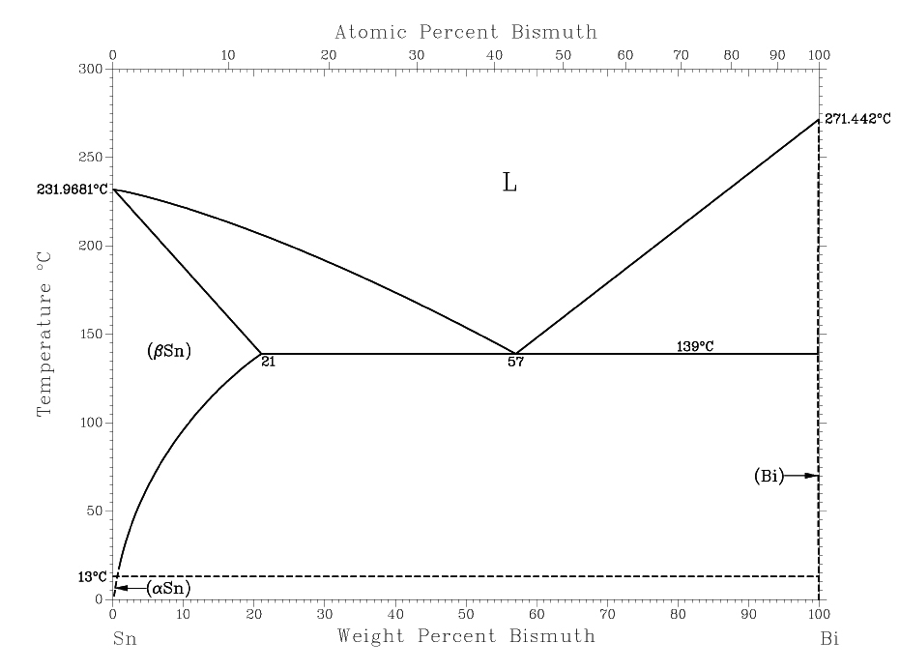
Fig. 7 THE BISMUTH-TIN PHASE DIAGRAM The diagram is based on published data (e.g. M.Hansen & K. Anderko, 'constitution of inary Alloys;' .J. Smithells, "Metals Reference Book"). There is a slight uncertainty in the eutectic composition, with most reports in the range of 42-43% Tin. The Alloy MCP 137 contains 42% Tin.
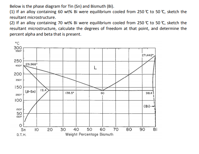
Solved Below Is The Phase Diagram For Tin Sn And Bismuth Chegg Com
SOLIDIFICATION: BISMUTH-TIN COOLING CURVE 13 Figure 16: Phase diagram of the Bi-Sn alloy from literature (Adapted from Yeh et al., 2011). Conclusion The structure of the alloy showed the same features that the literature was reporting. The slight difference might have resulted from the fluctuating cooling temperatures. The cooling curves were also representing the solidification process that ...
Determination Of The Bismuth Tin Bi Sn Phase Diagram By Differential Scanning Calorimetry Steemit
on Bismuth Tin Phase Diagram. Diagram Type: binary phase diagram. Concentration range: full composition; 0- at.%. Sn. Temperature: - °C. Nature of investigation. Bio Hi everyone, my name is Josh and this is my first post, it is quite long but I hope you find it informative. by engenuity. 3 Metals Bi - Sn - Zi.

Binary Phase Diagrams And Thermodynamic Properties Of Silicon And Essential Doping Elements Al As B Bi Ga In N P Sb And Tl Abstract Europe Pmc
A binary system of tin/indium (Sn/In) in the form of nanoparticles was investigated for phase transitions and structural evolution at different temperatures and compositions. The Sn/In nanosolder particles in the composition range of 24-72 wt% In were synthesized by a surfactant-assisted chemical reduction m
Tajhizkala Ir
The elements bismuth and indium have relatively low melting points when compared to other metals, and their alloy Bismuth Indium is classified as a fusible alloy. It has a melting point lower than the eutectic point of the tin lead alloy. The Bi-Sn phase diagram in [Massalski2] was adopted from [Hansen], who assessed the Bi-Sn phase diagram ...
Green Fabrication Of Stable Lead Free Bismuth Based Perovskite Solar Cells Using A Non Toxic Solvent Communications Chemistry
Oct 31, 2004 · The phase diagram was determined by XRD at 25 °C for conventionally sintered and unpoled ... Bismuth layer-structured plate-like Bi 2.5 Na 3.5 Nb 5 O ... tin oxide and lead titanate-lead hafnate. ...
Experiment And Results
The elements bismuth and indium have relatively low melting points when compared to other metals, and their alloy bismuth-indium (Bi-In) is classified as a fusible alloy.It has a melting point lower than the eutectic point of the tin-lead alloy. The most common application of the Bi-In alloy is as a low temperature solder, which can also contain, besides bismuth and indium, lead, cadmium ...
Solid Liquid Phase Diagrams Tin And Lead
Bi-Sn (Bismuth-Tin) The Bi-Sn phase diagram in [Massalski2] was adopted from [Hansen], who assessed the Bi-Sn phase diagram data published before 1958. Since then, more experimental data on this system were reported by [ 1958Oel ], [ 1969Del ], [ 1987Gla ], and [ 2007Bra ].
Dl Asminternational Org
3-Dimensional Depiction of Temperature-Composition Phase Diagram of Bismuth, Tin, and Lead at 1atm.The diagram has been simplified by omission of the regions of solid solubility. Each face of the triangular a eutectic. There is also a peritectic point in the Bi-Pb phase diagram.Figure by MIT OCW.

Question 3 Consider 2 Kg Of Tin Bismuth Alloy Sn Bi Containing 30 Wt Bi The Phase Diagram Homeworklib
Tin is a post-transition metal in group 14 of the periodic table of elements. It is obtained chiefly from the mineral cassiterite, which contains stannic oxide, SnO 2. Tin shows a chemical similarity to both of its neighbors in group 14, germanium and lead, and has two main oxidation states, +2 and the slightly more

Tin Bismuth Equilibrium Phase Diagram Chand 1 Tin Bismuth Equilibrium Phase Diagram Gurgagn Chand Ahmet Arslan Zhaoning Chen Eng 45 Section A04 1 26 Course Hero
Bismuth -cadmium system. KCl -CaCl 2 system. Benzene - methyl chloride system. KI -H2O system. Lead -silver system. Lead -silver system. o It is an example for two components system. o Its phase diagram forms a simple eutectic point. o The eutectic point can be represented by point C in the above figure.

Effect Of Antimony Additions On Corrosion And Mechanical Properties Of Sn Bi Eutectic Lead Free Solder Alloy
Bismuth is a chemical element with the symbol Bi and atomic number 83. It is a post-transition metal and one of the pnictogens with chemical properties resembling its lighter group 15 siblings arsenic and antimony.
1
Tin Bismuth Phase Diagram - Crystals Free Full Text. tin tin is a chemical element with the symbol sn from latin stannum and atomic number 50 it is a post transition metal in group 14 of the periodic table. Tin Bismuth Phase Diagram - Crystals Free Full. properties of water hydrogen hydroxide hh or hoh hydrogen oxide dihydrogen monoxide ...

Bismuth Wikipedia
The tin-bismuth phase diagram Composition of the Bi-Sn soldier: 57wt% Bi Questions: 1. Give the names for the single phases in the Sn-Bi system 2. To fíll the name for each phase region 3. The eutectic temperature and the eutectic composition 4. T m for pure Sn and Bi Chapter 9 - 18

The Phenomenon Of Tin Pest A Review Sciencedirect
Alpha Tin The alpha phase of tin (white tin) exists below 13.2˚C and is shown on the tin-bismuth phase diagram located near the end of this document. The room temperature phase, βSn, is located in the large triangular region on the left of the diagram. αSn does not appear on the lead-tin diagram used in the
Solved Below Is The Phase Diagram For Tin Sn And Bismuth Chegg Com
Transcribed image text: A phase diagram for Tin (Sn) - Bismuth (BI) alloys is shown below: Atomic Percent Bismuth 20 30 40 50 60 70 80 90 100 300 271442°C 250 231.9681°C 200 Temperature °C (81) 150 139°C (Sn) 21.0 57 99.9 100 10 50 70 60 Weight Percent Bismuth 100 DI Sn (a) What's the weight composition at the eutectic point on the phase diagram [Select) (b) At a state point of 40wt% BI ...

Sodium Tin System Thermodynamic Properties Of Alloys And Prospects For Using Tin And Its Alloys And Compounds In Sodium Ion Batteries Review Semantic Scholar
84Sak: T. Sakurai, "Construction of the Bi−Pb−Sn Ternary Phase Diagram by Means of Thermal Analysis," dissertation (GIF049), School of Science and Engineering, Waseda University, Japan (1984) in Japanese. (Ternary System; Experimental; Indicates presence of a phase diagram)

Phase Diagram Of Tin Bismuth Download Scientific Diagram
Allen and Jesser [49] evaporated 99.99% Bi and Sn on amorphous C films to make alloys with 40 nm grains, and observed them via using in situ TEM. Fig. 7.7 shows one of their phase diagrams. The solid and dashed lines show the phase diagrams of conventional and nanoalloys, respectively. In each of the nanoalloy phase diagrams the solidus and liquidus fully move down; therefore the melting point ...

Eutectic Phase Diagram
Status of the thermodynamic description: B.-J. Lee, C.-S. Oh and J.-H. Shim, J. Electron. Mater. 25 (1996) 983-991: Full thermodynamic assessment.
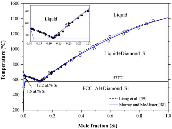
Materials Free Full Text Binary Phase Diagrams And Thermodynamic Properties Of Silicon And Essential Doping Elements Al As B Bi Ga In N P Sb And Tl Html
Phase Diagrams • Indicate phases as function of T, Co, and P. • For this course:-binary systems: just 2 components.-independent variables: T and Co (P = 1 atm is almost always used). • Phase Diagram for Cu-Ni system Adapted from Fig. 9.3(a), Callister 7e. (Fig. 9.3(a) is adapted from Phase Diagrams of Binary Nickel Alloys , P. Nash
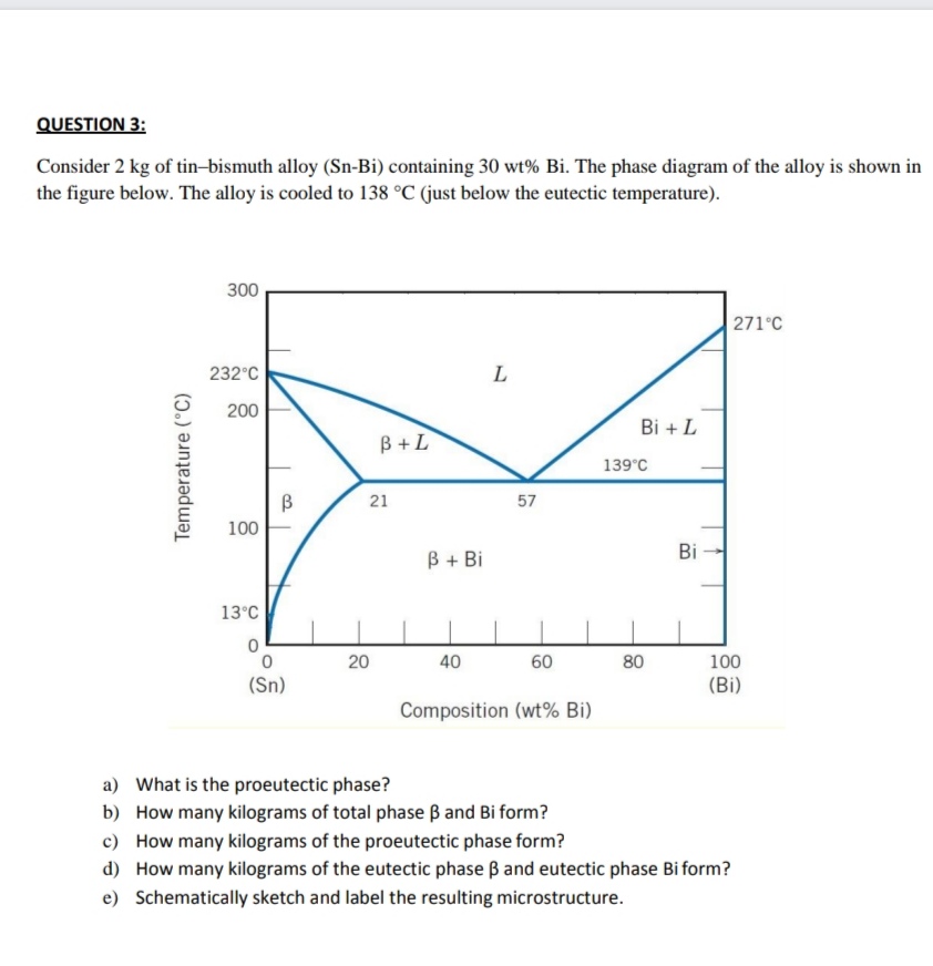
Answered Question 3 Consider 2 Kg Of Bartleby
Solid Liquid Phase Diagrams Tin And Lead
Jim Or Jp

Solved Consider The Hypothetical Eutectic Phase Diagram For Metals A 1 Answer Transtutors
Oecd Nea Org

The Sn Bi Bulk Phase Diagram 20 Points Show The Compositions Of The Download Scientific Diagram

Calorimetric Study On Bi Cu Sn Alloys

Phase Diagram Of The Pb Bi Alloy Download Scientific Diagram

Essential Magnesium Alloys Binary Phase Diagrams And Their Thermochemical Data

Prediction And Characterization Of Heat Affected Zone Formation In Tin Bismuth Alloys Due To Nickel Aluminum Multilayer Foil Reaction Journal Of Applied Physics Vol 117 No 24
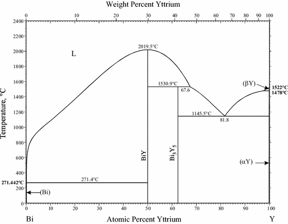
Supplemental Literature Review Of Binary Phase Diagrams Bi Ga Bi Y Ca H Cd Fe Cd Mn Cr La Ge Ru H Li Mn Sr Ni Sr Sm Sn And Sr Ti Springerlink

Binary Compounds Of Silicon Wikipedia
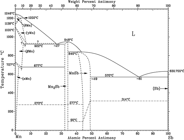
Experimental Investigation Of The Binary Mn Sb Phase Diagram Springerlink

Thought Crackers Sep 26 2015

Binary Phase Diagrams And Thermodynamic Properties Of Silicon And Essential Doping Elements Al As B Bi Ga In N P Sb And Tl Abstract Europe Pmc
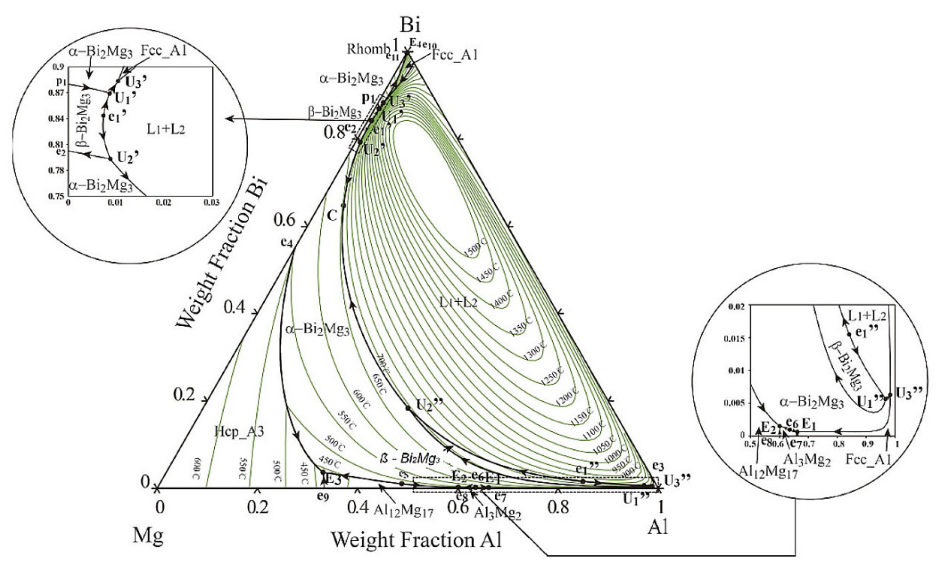
Crystals Free Full Text Mechanism Of The Mg3bi2 Phase Formation In Pb Free Aluminum 6xxx Alloy With Bismuth Addition Html
1
0 Response to "37 tin bismuth phase diagram"
Post a Comment