37 how to read pressure enthalpy diagram
4.88 pressure-enthalpy diagram for ethylene 10 100 1000 10000 700 750 800 850 900 950 1000 1050 1100 1150 1200 enthalpy, Btu/lb pressure (psia) 160 F 140 F 120 F 100 F 80 F 60 F 40 F 20 F 0 F 20 F 240 F 200 F 100 F 0 F 100 F 200 F 300 F liquid liquid-vapor two phase vapor psia = pounds per square inch absolute A "good" service technician can find the usual problem - it takes a "very good" service technician to find the unusual! Knowing how to construct and interpret a pressure enthalpy (PH chart separates the good technician from the very good service engineer. Figure 1 is a PH diagram for R-22 refrigerant.
A p-h diagram is a figure with a vertical axis of absolute pressure and a horizontal axis of specific enthalpy. It is an important diagram used frequently for a performance calculation of a refrigerating machine. A p-h diagram is made respectively for a specified refrigerant. It can, of course, not be used for another refrigerant.
How to read pressure enthalpy diagram
Pressure / Enthalpy Diagram Example. This article was written by my buddy and Canadian Supertech Tim Tanguay. Thanks, Tim! This P/E chart shows R410a at 100°F saturated condensing temp, 10°F SC, 40°F saturated suction temp, 20°F SH at the compressor. The green highlighted thumb shape is the saturation zone. Reading the liquid-vapor dome section of a pressure-enthalpy diagram. LIQUID VAPOR DOME. The shaded dome-like region outlines when the compound is both a mix of saturated liquid and saturated vapor. The tip of the dome marks the critical point. The area to the ... Mollier enthalpy-entropy chart for steam, US units. Image credit: Emok. The Mollier diagram is a tool used by engineers to predict, theoretically, the performance of systems and installations. The Mollier diagram, also called the enthalpy (h) - entropy (s) chart or h-s chart, is a graphical representation of thermodynamic properties of materials.
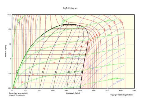
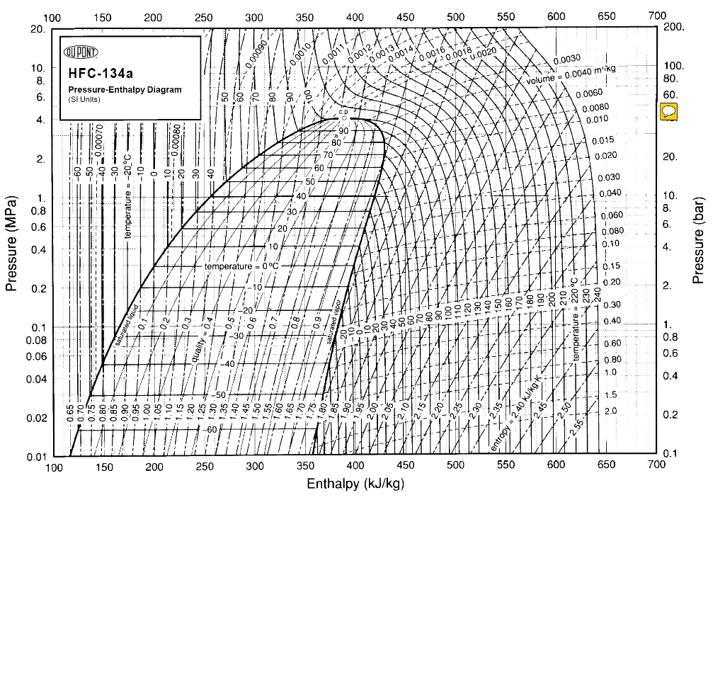
How to read pressure enthalpy diagram. tecquipment.com Pressure-Enthalpy chart, R-134a (1,1,1,2-tetrafluoroethane) Enthalpy (kJ/Kg) Pressure (Bar) Pressure (MPa) Produced by TecQuipment's VDAS ® system The Pressure-Enthalpy Diagram is useful tool for refrigerant technicians. It can be seen as a map of the refrigerant. It allows to show, how thermodynamic pr... How to Read a Pressure-Enthalpy Diagram In chemical engineering, it is often necessary to know how properties like pressure, enthalpy, volume, and entropy relate to each other at a certain temperature. A Pressure-Enthalpy Diagram provides this information but can be cryptic to decipher. What you need to know: Liquid/vapor dome region critical pressure can condense the vapor into a liquid. In the case of R-22, the critical temperature is 205.24°F (some pressure-enthalpy diagrams show the critical temperature as 204.81°F) and the critical pressure is 722.39 psia.The critical point for R-410A occurs at 161.83°F and 714.5 psia. Notice that a reference point for enthalpy is ...
Engineering. Chemical Engineering. Chemical Engineering questions and answers. PLEASE UPLOAD Pressure-enthalpy diagram for ARGON. Pressure-Enthalpy Diagram for R134a Refrigerant An enthalpy diagram allows us to easily see details of a chemical reaction. By knowing how to draw and label an enthalpy diagram we can see what the starting energy level is, how much energy is ... This video explains the parts of a pressure-enthalpy diagram for a single-component system and discusses how enthalpy depends on pressure for water. If these diagrams are a breeze for you, or you're just looking for help with another concept, check out other chemical engineering tutorials in the Learn ChemE Engineering Screencast series .
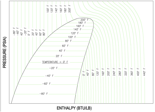
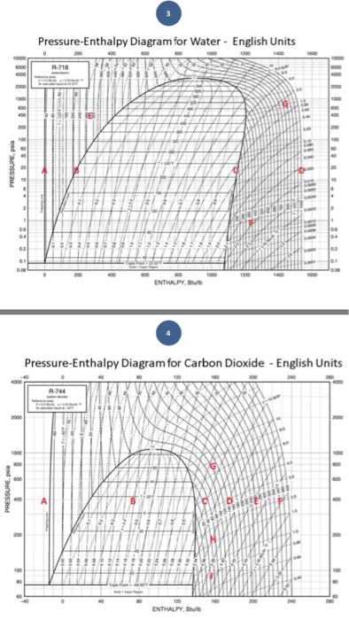
pressure is read on the vertical scale along the left side. Enthalpy (heat content) is read on the bottom scale at a number of different temperatures. To the right is a curve representing saturated vapor. This is vapor associated with liquid, and the type of vapor found in a refrigerant cylinder, a condenser, or a flooded evaporator. Carbon Dioxide: Pressure - Enthalpy Diagram Melting Line-40 o -40 C-2 0-2 0. Title: mollier_chart_met.xls Created Date: 11/10/1999 5:42:45 PM A Pressure-Enthalpy Diagram provides this information but can be cryptic to decipher. What you need to know: Liquid/vapor dome region Reading vapor fraction The Lever Rule Reading pressure Reading enthalpy Reading temperature Reading entropy Reading volume. LIQUID VAPOR DOME. R410A Pressure Enthalpy Chart. Scroll down to download a PDF copy of the pressure enthalpy chart for both Metric and Imperial Units. These charts were provided courtesy of Danfoss, using their FREE CoolSelector 2 software.
P H Diagram Thermodynamics Hvac And Refrigeration Pe Exam Tools Mechanical And Electrical Pe Sample Exams Technical Study Guides And Tools
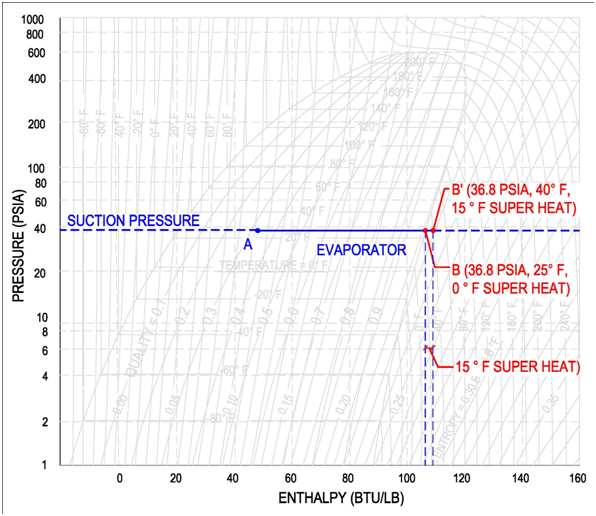
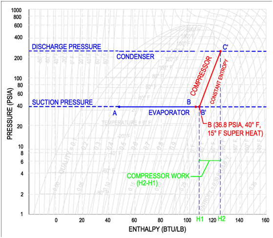
On the pressure-enthalpy diagram superheat is shown as horizontal movement along the suction pressure line passed the 100% vapor curve. The figure on the following page shows the difference between 0 °F and 15 °F superheat. Point B is the 100% vapor point at a constant evaporator/suction pressure of 36.8 psia and a temperature of 25 °F.

Low Charge And The Pressure Enthalpy Diagram Fundamental Refrigeration
The pressure-enthalpy diagram (log P/h diagram) is a very useful tool for refrigerant technicians. First, an explanation of how the diagram is built up is given, and then its use is describ ed. Figure 2.1 shows the principle of a log P/h diagram, and indicates the refrigerant's various thermodynamic states.

Pressure Enthalpy Diagram Evaporation Youtube
The pressure-enthalpy diagram (log P/h diagram) is a very useful tool for refrigerant technicians. The area below the saturation lines for liquid and gas (A-CP-B in Figure 2.1) represents the conditions where the refrigerant can change its state of aggregation from liquid to gas or vice versa.
Using Mollier S Chart What Is The Final Pressure And Temperature Of Steam When It Is Isentropically Expanded From Enthalpy Of 3500 Kj Kg And 30 Bar Pressure To Enthalps Of 2900 Kj Kg Quora
There is much information you can get from reading a pressure enthalpy diagram. Included is the liquid/vapor dome region, reading vapor fraction, the Lever Rule, reading pressure, reading enthalpy ...
How To Read Mollier Diagram Easy Explain Youtube
The Mollier diagram is a graphic representation of the relationship between air temperature, moisture content and enthalpy, and is a basic design tool for building engineers and designers. Download and print Mollier diagram. common psychrometrics terms. The Mollier diagram is a variant of the psychrometric chart.
Reading Thermodynamic Diagrams
Enthalpy [kJ/kg] Pressure [MPa] Methane Pressure-Enthalpy Diagram S=Specific Entropy, kJ/kg*K T=Temperature, ºC T=-160 T=-150 T=-140 T=-130 T=-120 T=-110 T=-100 T=-90 T=-170 T=-100 T=-50 T=0 T=50 T=100 T=150 T=200 Produced by I. Aartun, NTNU 2002. Based on the program Allprops, Center for Applied Thermodynamic Studies, University of Idaho. S ...
P H Diagram Thermodynamics Hvac And Refrigeration Pe Exam Tools Mechanical And Electrical Pe Sample Exams Technical Study Guides And Tools
This case is to review the practical use of the Pressure-Enthalpy (P-H) diagram and the thermodynamic analysis of the refrigeration cycle using the P-H diagram; the Refrigerant Flow Diagram corresponding to the P-H Diagram. This case is also to evaluate various cycles such as with penalties, economizing for a

Pressure Enthalpy Chart
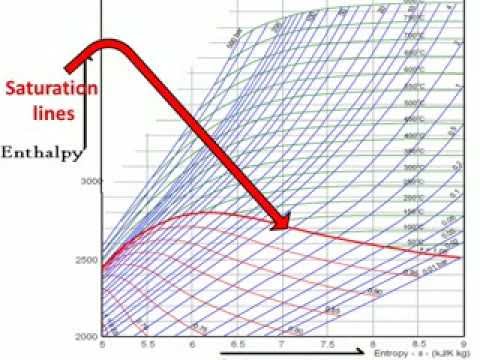
The Mollier diagram is a is plot of enthalpy (h) versus entropy (s) as shown in Fig. 21.1. It is also known as the h-s diagram. This diagram has a series of constant temperature lines, constant pressure lines, constant quality lines, and constant volume lines. The Mollier diagram is used only when quality is greater than 50% and for superheated ...

2 1 The Pressure Enthalpy Diagram Swep
The term "Mollier diagram" (named after Richard Mollier, 1863-1935) refers to any diagram that features Enthalpy on one of the coordinates. Commonly used Mollier diagrams are the enthalpy-entropy (or h-s) diagram ( below) and the pressure-enthalpy diagram illustrated at the bottom of this page. The h-s diagram is one in which Enthalpy ...

2 1 The Pressure Enthalpy Diagram Swep
This screencast has been updated. Please see the revised version here: https://youtu.be/jGIHNKLMLCY Made by faculty at the University of Colorado Boulder, D...
Analysis Of The Mollier Diagram To Simplify The Calculations Of Thermodynamic Magnitudes Steemit
The diagrams shown include pressure-temperature, pressure-volume, temperature-volume, temperature-entropy, pressure-enthalpy, and enthalpy-entropy. Description : Describes the regions of a liquid-solid, T-x Si phase diagram for a system composed of Mg and Si.

Appendix D Pressure Enthalpy Diagrams For Various Compounds Chemical Engineering Fluid Mechanics 3rd Edition Book
The pressure-enthalpy chart, as shown in Fig. 2, displays all the pertinent properties for a given refrigerant (in this example R22). The bubble to the left is the portion of the diagram where the refrigerant is in the saturated condition. The blue line on the left of the bubble represents the 100% saturated liquid line,
Solved 200 100 150 20 10 Hfc 134a Pressure Enthalpy Diagram Chegg Com
Mollier enthalpy-entropy chart for steam, US units. Image credit: Emok. The Mollier diagram is a tool used by engineers to predict, theoretically, the performance of systems and installations. The Mollier diagram, also called the enthalpy (h) - entropy (s) chart or h-s chart, is a graphical representation of thermodynamic properties of materials.
1
Reading the liquid-vapor dome section of a pressure-enthalpy diagram. LIQUID VAPOR DOME. The shaded dome-like region outlines when the compound is both a mix of saturated liquid and saturated vapor. The tip of the dome marks the critical point. The area to the ...

Pressure Enthalpy P H Diagram Of Reefer Container The Pressure Download Scientific Diagram
Pressure / Enthalpy Diagram Example. This article was written by my buddy and Canadian Supertech Tim Tanguay. Thanks, Tim! This P/E chart shows R410a at 100°F saturated condensing temp, 10°F SC, 40°F saturated suction temp, 20°F SH at the compressor. The green highlighted thumb shape is the saturation zone.
Refrigeration Basics Definitions Part 2

Pressure Enthalpy Graph Showing Different Points Download Scientific Diagram
Agc Chemicals Com
1
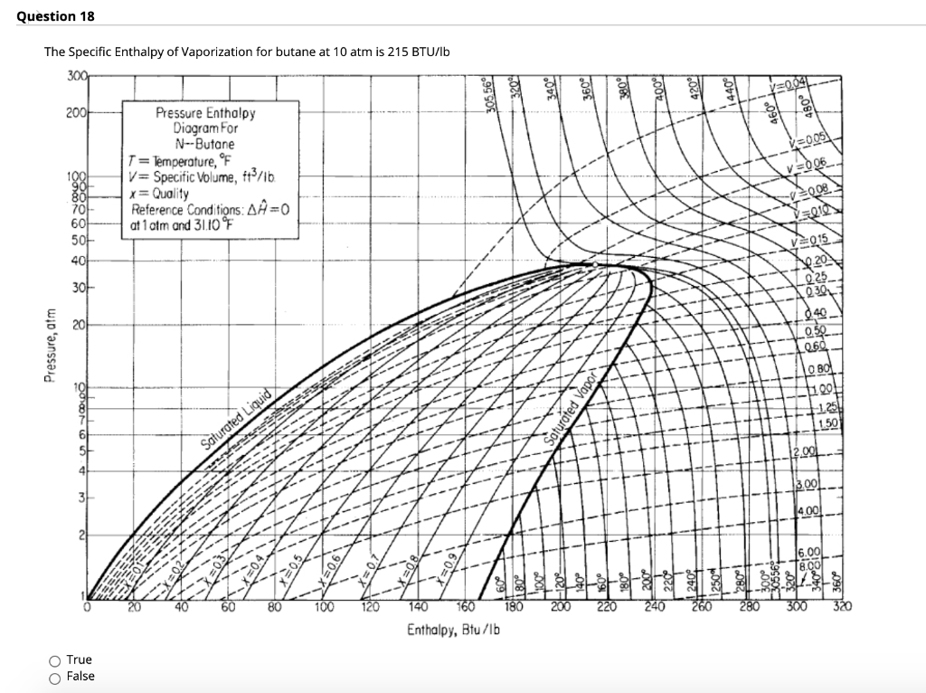
Solved Question 18 The Specific Enthalpy Of Vaporization For Chegg Com

Refrigerants P H Diagram Refrigeration Hvac R And Solar Energy Engineering
Solved 1 Of 4 Pressure Enthalpy Diagram For Water Si 200 Chegg Com

Mollier Chart How To Read Youtube
Moist Air The Mollier Diagram

Understanding The Ph Chart Enthalpy Chart Youtube

Pressure Enthalpy Diagram For R134a Refrigerant

Pressure Enthalpy Charts Industrial Controls
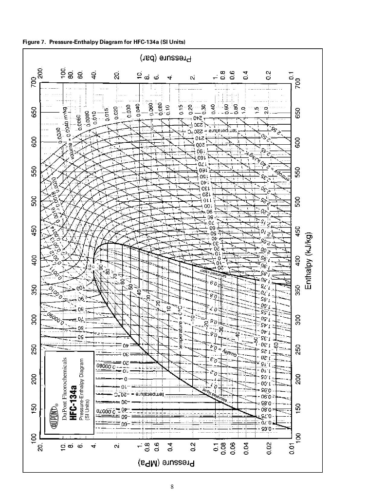
Solved Figure 7 Pressure Enthalpy Diagram For Hfc 134a Si Chegg Com
Peer Asee Org

Pressure Enthalpy Diagram
Pdfcoffee Com
Mollier Diagram
Ph Scale Diagram
P H Diagram Thermodynamics Hvac And Refrigeration Pe Exam Tools Mechanical And Electrical Pe Sample Exams Technical Study Guides And Tools
Tecquipment Com
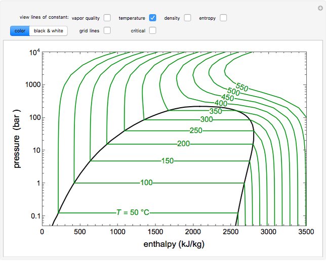
Pressure Enthalpy Diagram For Water Wolfram Demonstrations Project

Efficiency Measuring Refrigeration
0 Response to "37 how to read pressure enthalpy diagram"
Post a Comment