36 what is context diagram
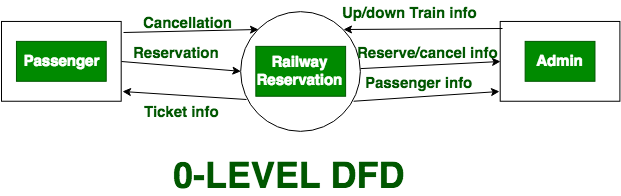
Here, we will see mainly 3 levels in the data flow diagram, which are: 0-level DFD, 1-level DFD, and 2-level DFD. 0-level DFD: It is also known as a context diagram. It’s designed to be an abstraction view, showing the system as a single process with its relationship to external entities. It represents the entire system as a single bubble ... The context diagram helps you to identify the interfaces you need to account for, helps you to identify scope, identify potential stakeholders, and build a better understanding of the context in which you are working. The context diagram is also known as the context data flow diagram or level 0 data flow diagram. Elements of a context diagram.
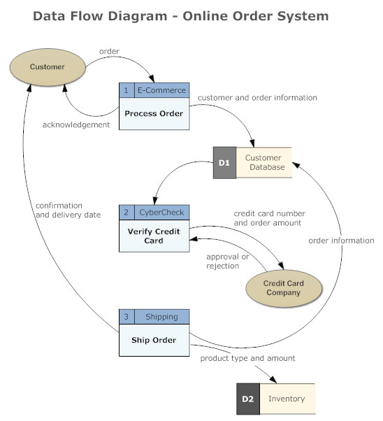
A Data Flow Diagram shows what information is sent as an input and what information comes as an output and where the next information will go. It is a best practice to draw the context level data flow diagram of any system first which provides information on system's interactions with the external environment and boundaries of system in terms ...

What is context diagram
The context diagram of a vision document is a simple diagram that shows the source systems contributing data to a DW/BI system, as well as the major user constituents and downstream information systems that is supports. This simple diagram only takes a few minutes to draw once the project architect has completed all the research and the hard thinking that it represents. Answer (1 of 2): In the UML, a context diagram is used to display how a system relates to its environment (users, related systems, etc.). For example, if I'm working on an order processing application, I might start out with a context diagram. In the middle of the diagram would be a box symboliz... context diagram can be one of the options to accompany you once having extra time. It will not waste your time. give a positive response me, the e-book will utterly tell you other concern to read. Just invest tiny time to admittance this on-line statement inventory management system context diagram as without difficulty as evaluation them ...
What is context diagram. What are the parts of a context diagram? Context diagrams are made up of simple parts: boxes and lines. According to Wikipedia, "Context diagrams can be developed with the use of two types of building blocks: labeled boxes, one in the center representing the system and around it multiple boxes for each external actor, and relationship, labeled lines between the entities and system".[6] A context diagram is a visual representation of the relationship between data and business processes. This diagram has 3 main components which include external entities, system processes, and data flows. It provides the factors and events you need to consider when developing a system. With it, you will be able to determine the scope, boundaries ... A diagram used to give an overview of an entire system. In a context diagram there is only one circle / process that represents the entire system. The purpo... PG Public Services, LLC 3 Business Context Diagrams Introduction A business context diagram (BCD) is a one‐page
The objective of the system context diagram is to focus attention on external factors and events that should be considered in developing a complete set of systems requirements and constraints. A system context diagram is often used early in a project to determine the scope under investigation. Thus, within the document. A system context diagram represents all external entities that may interact with a system. The entire software system is shown as a single process. Such a diagram pictures the system at the center, with no details of its interior structure, surrounded by all its External entities, interacting systems, and environments. Here is an example context diagram for a Sale Order System: Edit this Diagram A system context diagram (SCD) in engineering is a diagram that defines the boundary between the system, or part of a system, and its environment, showing the entities that interact with it. This diagram is a high level view of a system.It is similar to a block diagram Context Diagram. A context diagram helps in understanding the entire system by one DFD which gives the overview of a system. It starts with mentioning major processes with little details and then goes onto giving more details of the processes with the top-down approach. The context diagram of mess management is shown below. Data Dictionary What is context diagram in DFD? A context diagram is a top level (also known as "Level 0") data flow diagram. It only contains one process node ("Process 0") that generalizes the function of the entire system in relationship to external entities.
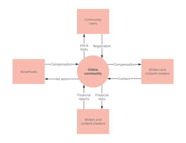
Q: business example: precision tools sells a line of high-quality woodworking tools. when customers pla... A: Context diagram: A context diagram is said to be the least detailed data flow diagram, which will p... A context diagram is a data flow diagram, with only one massive central process that subsumes everything inside the scope of the system. It shows how the system will receive and send data flows to the external entities involved. The core element of a context diagram is a circle, or bubble, representing your system. This basic shape sits at the center of the diagram and doesn’t show the internal workings of the process. You’ll be creating your context diagram at the early stages of design, so you can consider the system to be a “black box”. You don’t need to think about what’s inside. Next up are the real-world external entities that interact with your system. You represent these with rectangles and nouns to describe their role. These entities will exchange data with your system. They might be users, companies, or other systems. You also don’t need to worry about their internals, just that they will be involved. Once you have your system and the entities that will interact with it, you can start to map out the flow of data. Lines between the entities and your system show the exchange of data. Arrows represent the direction of data flow. The Context Diagram shows the system under consideration as a single high-level process and then shows the relationship that the system has with other external entities (systems, organizational groups, external data stores, etc.). Another name for a Context Diagram is a Context-Level Data-Flow Diagram or a Level-0 Data
Pengertian Dan Contoh Context Diagram Cd Vebry Exa P Blog
What is context diagram in DFD draw DFD up to 1st level of online examination? A DFD can be categorized in the following forms: Context diagram: An overview of an organizational system that shows the system boundaries, external entities that interact with the system and the major information flows between the entities and the system.

Context Diagram Vs Affinity Diagram Pm Vidya
A context diagram, sometimes called a level 0 data-flow diagram, is drawn in order to define and clarify the boundaries of the software system.It identifies the flows of information between the system and external entities. The entire software system is shown as a single process.

Context Diagram Youtube
A context diagram is still a useful diagram to create in developing a game, it's just not as useful as when developing an information based system. Creating a Context Diagram. Creating a context diagram is easy. Creating a context diagram which is an accurate representation of your system can be hard.

Data Flow Diagrams
Context diagrams are an excellent tool for facilitating brainstorming among those design and analyze them. A context diagram is suitable for noting omissions and blunders in a business plan or project requirements. Hence you can make necessary corrections and adjustments before the project execution and reduce project risks.

Data Flow Diagram System Context Diagram Angle Text Png Pngegg
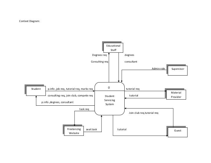
A context diagram is a top level (also known as "Level 0") data flow diagram. It only contains one process node ("Process 0") that generalizes the function of the entire system in relationship to external entities. DFD Layers. Draw data flow diagrams can be made in several nested layers.
Systems And The Context Level Data Flow Diagram
The context diagram is used to establish the context and boundaries of the system to be modelled: which things are inside and outside of the system being modelled, and what is the relationship of the system with these external entities. A context diagram, sometimes called a level 0 data-flow diagram, is drawn in order to define and clarify the ...

Order System Context Diagram With Customers Management And Accounting Powerpoint Shapes Powerpoint Slide Deck Template Presentation Visual Aids Slide Ppt
Download the document template from here Architecture_Context_Diagram_appName.pptx. The template contains an example, shown below, of what is required. If an equivalent diagram already exists which shows what is required then provide that instead of creating a new diagram. Create the diagram in the template as explained below.

Context Level Diagram Exmaple
Level 1 DFDs are still a general overview, but they go into more detail than a context diagram. In a level 1 data flow diagram, the single process node from the context diagram is broken down into subprocesses. As these processes are added, the diagram will need additional data flows and data stores to link them together.
1
Context diagrams. A context diagram is a graphical representation of a system which must only use one process to represent the entire system and deliberately does not go into defining all the processes so as to prevent people getting bogged down in complex details at an early stage.
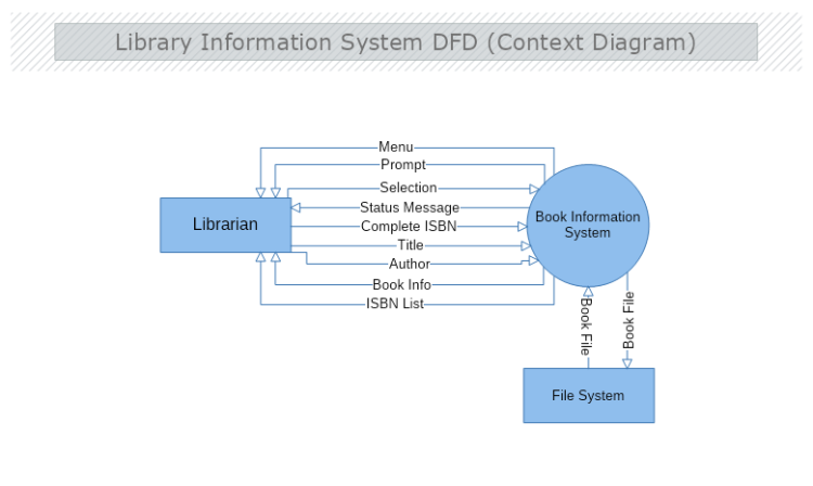
Library Information System Context Data Flow Diagram Mydraw
Context data flow diagram (also called Level 0 diagram) uses only one process to represent the functions of the entire system. It does not go into details as marking all the processes. The purpose is to express the system scope at a high level as well as to prevent users from deep down into complex details.

Management System Context Diagram With Vendors And Manager Powerpoint Templates Download Ppt Background Template Graphics Presentation
A Context Diagram is also referred to as a Level-0 Data Flow Diagram or a Top-Level Data Flow Diagram. This essentially means that context diagrams can be described in DFD terminology. Level-0 Data Flow Diagrams consist of a single process node and are generally devoid of details about the working of the system.
Context Diagrams Free Management Books
A Context Diagram (sometimes also referred to as a Level-0 Data Flow Diagram) is a common tool that Business Analysts use to understand the context of an entity being examined. Most descriptions of a Context Diagram limit this entity to a system that is being created or modified as part of a project, but the Context Diagram can also be applied ...

Context Diagrams An Explanation
Context Switching involves storing the context or state of a process so that it can be reloaded when required and execution can be resumed from the same point as earlier. This is a feature of a multitasking operating system and allows a single CPU to be shared by multiple processes. A diagram that demonstrates context switching is as follows −.

System Context Diagram Wikipedia
A context diagram, sometimes called a level 0 data-flow diagram, is drawn in order to define and clarify the boundaries of the software system. It identifies the flows of information between the system and external entities. The entire software system is shown as a single process.
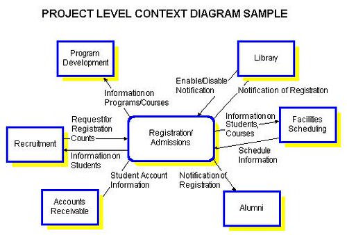
Context Diagrams At The Project Level Toolbox Tech
Context-Free Grammar Subjects to be Learned. Context-Free Grammar Context-Free Languages ... ( q , a , X ) = ( p , ) , then an arc from state p to state q is added to the diagram and it is labeled with ( a , X / ) indicating that X at the top of the stack is replaced by upon reading a from the input. For example the transition diagram of the ...

What Is A System Context Diagram With Explanation Examples
The context diagram provides different views of information system. Diagram 0 is used to provide insight view of an info system represents internal process, entities, data flow, and data storage. Data stores are not used in a context diagram.

Context Diagram Ist Project Management Office University Of Waterloo
Context diagrams are visual tools that depict the scope of the product showing the business system and how it relates and interacts with the other systems as well. It is a good example of a project management scope model. It shows the inputs to the system, the main players that provide the input as well as the output of the system and the actors receiving them.
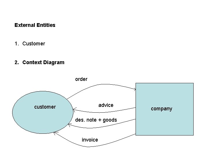
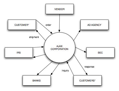
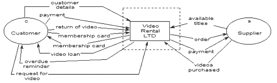
Data Flow Diagrams Context Diagram Order Company Customer
Summary Logical vs Physical DFD. Note that the Context Diagram did NOT record the movement of merchandise, but rather the information flow surrounding the underlying business processes. Let's summarize their differences: A DFD that shows the movement of information is called a logical DFD.; A DFD that shows the movement of physical stuff (such as merchandise) is called a physical DFD.
What Is A Context Diagram With Examples Edrawmax Online
context, interactions, structure and behavior. • Context models show how a system that is being modeled is positioned in an environment with other systems and processes. • Use case diagrams and sequence diagrams are used to describe the interactions between users and systems in the system being designed. Use

What Is A Data Flow Diagram Lucidchart
context diagram can be one of the options to accompany you once having extra time. It will not waste your time. give a positive response me, the e-book will utterly tell you other concern to read. Just invest tiny time to admittance this on-line statement inventory management system context diagram as without difficulty as evaluation them ...
Levels In Data Flow Diagrams Dfd Geeksforgeeks
Answer (1 of 2): In the UML, a context diagram is used to display how a system relates to its environment (users, related systems, etc.). For example, if I'm working on an order processing application, I might start out with a context diagram. In the middle of the diagram would be a box symboliz...

What Is A Data Flow Diagram Lucidchart
The context diagram of a vision document is a simple diagram that shows the source systems contributing data to a DW/BI system, as well as the major user constituents and downstream information systems that is supports. This simple diagram only takes a few minutes to draw once the project architect has completed all the research and the hard thinking that it represents.

System Context Diagram Description Examples Video Lesson Transcript Study Com
Context Diagrams Mcr Ipt
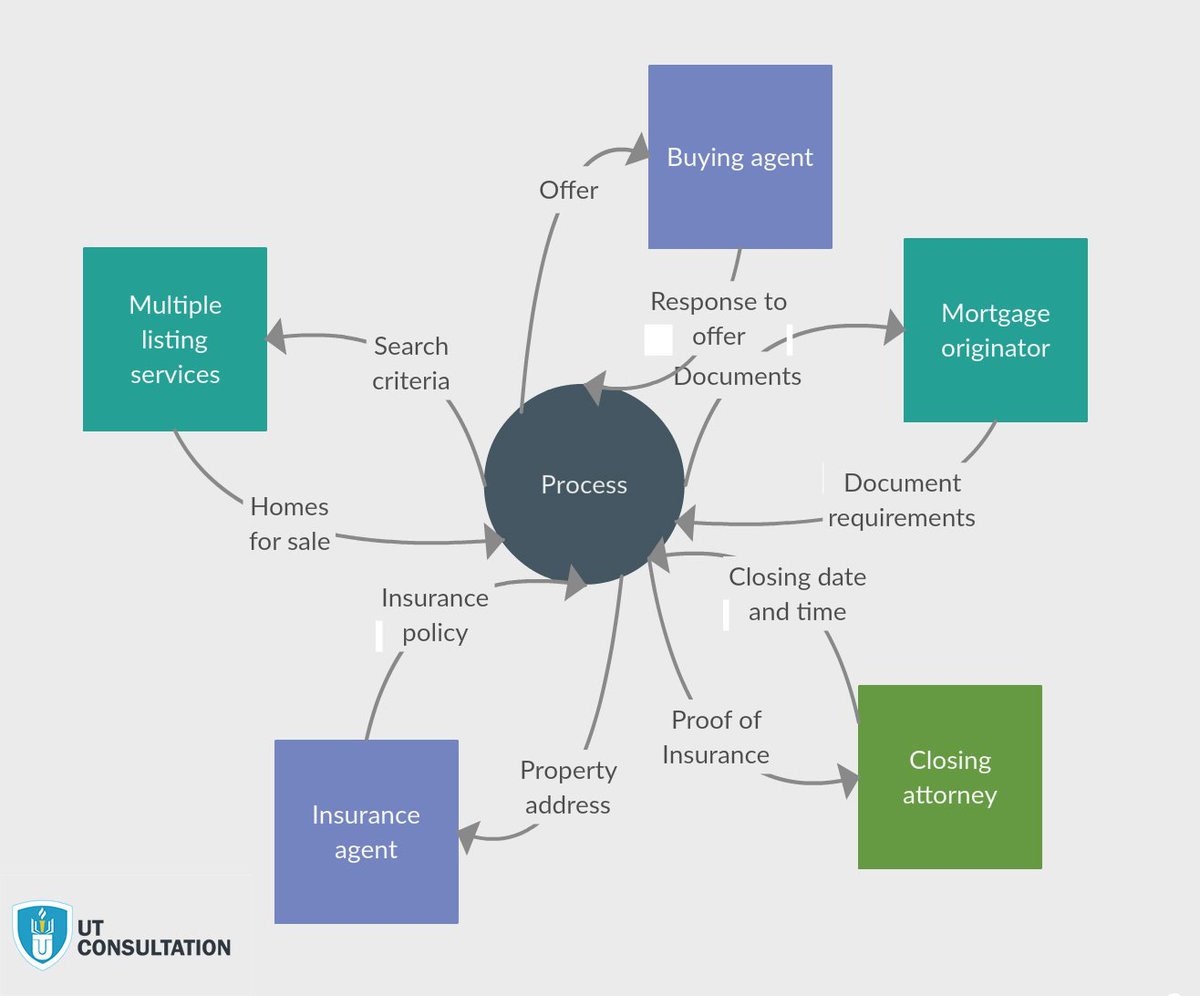
Utc Consultation Training Center On Twitter How To Effectively Use Context Diagram In Business Analysis Professional Pmi Pba Visit Our Website Https T Co Hmjfh9dxxb السعودية تدريب الرياض Https T Co Hmyg6dic3n

Pengertian Diagram Konteks Contoh Manfaat Dan Cara Membuatnya

File Nde Context Diagram Vector Svg Wikipedia
Context Diagrams
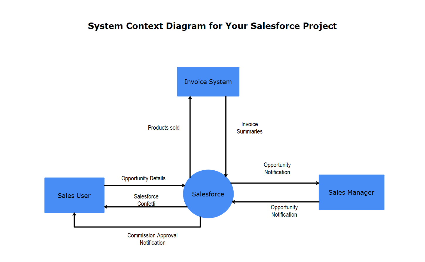
How To Create System Context Diagram

Context Diagram Rahmawatikrisdiana S Weblog
Data Flow Diagram Everything You Need To Know About Dfd
Gambar 1 Context Diagram Siomas Data Flow Diagram Dfd Download Scientific Diagram
What Is A Context Diagram With Examples Edrawmax Online

Context Diagram Of Inventory Management System Pdf Data Type Personal Identification Number
Context Diagram
Data Flow Diagram System Context Diagram Png 595x942px Diagram Area Big Data Chart Communication Download Free
0 Response to "36 what is context diagram"
Post a Comment