35 borg warner overdrive wiring diagram
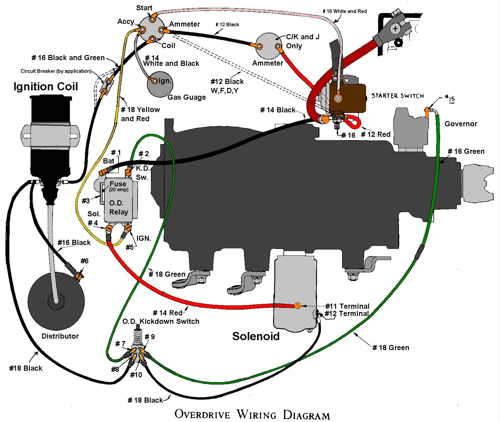
Borg Warner overdrive if ordered. One of the advantages of the Bert Hiller\Bil,1 Swigm1 overdrive is that they are sold as a complete kit. This includes the "T" handle cable, a 6 or 12 volt solenoid, a governor, a power relay, the speedometer cable extension, and the wiring and installation instructions. Borg Warner overdrives were Borg Warner Overdrive Wiring Diagram advance design restoration how to s advance design paint color information this is a pretty extensive listing of the mon colors for everything other than the outside colors sw em od retrofitting on a vintage volvo od retrofitting on a vintage volvo jun r kwas update on going my bw35 automatic to m Before ...
Location: Main Index » Forum Index » 55-57 Central » 1955-1957 Chevys (Stock / restored / show) » Overdrive Borg Warner R10 toggle switch wiring FusionBB™ Version 2.1 ©2003-2006 InteractivePHP, Inc.
Borg warner overdrive wiring diagram
Borg Warner Overdrive Wiring Diagram. Collection of borg warner overdrive wiring diagram. A wiring diagram is a streamlined standard photographic depiction of an electrical circuit. It reveals the parts of the circuit as simplified shapes, as well as the power as well as signal connections in between the gadgets. A wiring diagram normally offers details… Most of the other Borg-Warner overdrive units you will find are either R-10 or R-11 units. These could easily be bolted onto the tailshaft of any standard transmission of that era. There were four main electrical parts that activated these overdrive units: the relay, the switch, the solenoid and a governor; however, the solenoid was usually the ... the the overdrive lover, B. ELECTRICAL 14. a. While the of just may be considered working of its is by system, This system 01 by a the electrical practically of with there The wiring circuit wiring in the (Fig. S) applies K Willys and Nash (the With relay 1949 that the and to the Ignition switch, on the 1949 switch
Borg warner overdrive wiring diagram. 8 members ( Johnny N, Hotrod Lincoln, Gary42, Forty9, fdny330, 1 invisible), 145 guests, and 3 robots. I have been running a 3 speed W/overdrive on my 283 in the 58 Apache for 13 years now. I controlled it with a cable and a switch, bypassing the governor completely. I don't know how I lived without it. The electrical parts of the overdrive transmissions were also based on the same working theory, and most share the same basic wiring diagrams. In addition, all ... Understanding Borg-Warner's R-10/R-11 Overdrive Transmissions. Borg-Warner overdrive transmissions were first introduced in 1934, originally designed to reduce engine rpms at highway speeds. The early overdrive transmission is actually a two-speed planetary transmission attached to the rear portion of a standard three-speed transmission. I have mine wired stock, like in Tommy's diagram. The governor is a switch. It spins off a gear on the tailshaft and closes the circuit at around 26-28 mph. Pulling out the overdrive cable should be done only when stopped. The cable lock outs the overdrive so it operates like a standard 3 speed transmission with compression (engine) braking.
This is a diagram for wiring a split shift controlsetup for your T-85N transmission. This can beused for one you've bought outright and have nooriginal circuits ... Borg Warner Overdrive Wiring If you are lucky enough to land your mitts on a T-85N tranny, this page is for you! These were used in Studebakers, GM, and Ford cars and trucks. It gives your truck a semi-automatic tranny setup, and you will have a 3/4 split shift unit. The diagram below is for those of you who get a There are 3 or 4 switches in the wiring to get your overdrive to engage. If any one of those has failed your overdrive won't engage. In this video we will ru... Borg Warner Overdrive Wiring Diagram - wiring diagram is a simplified okay pictorial representation of an electrical circuit. It shows the components of the circuit as simplified shapes, and the knack and signal links between the devices. A wiring diagram usually gives information nearly the relative twist and promise of devices and terminals ...
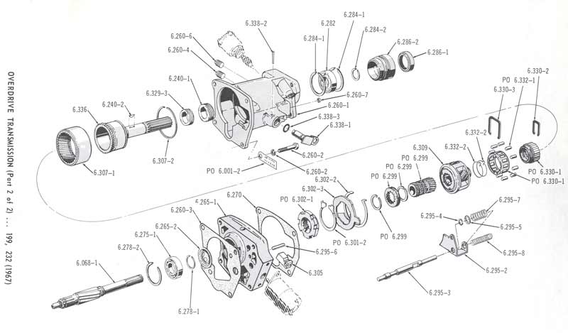
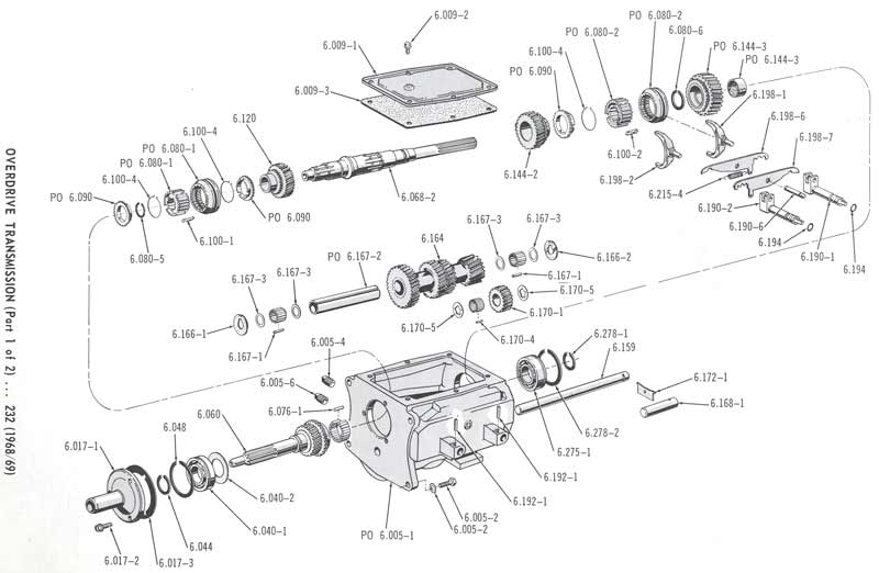
Rebuilding the Borg Warner Overdrive Unit. The rear case removed. This is the center section, and contains the rear bearing, linkage, solenoid mount, and gear assy for the overdrive. The transmission's main shaft is part of this unit, and it takes the place of the rear Borg Warner Overdrive Wiring Diagram. 1) Their were 11 different wiring diagrams for the Borg Warner overdrive transmission BESIDES the simple one I provide to you in my overdrive. Wire Harness Borg Warner Overdrive Transmission R10 & R11 Comes with wiring diagram showing how to wire for any electric OD application. Harness. Wiring Diagram For An R10 Borg Warner Overdrive. if you google R overdrive you will get a lot of help. If you look at the OEM wiring diagram you will see the biggest wire is 16 ga. Also the. 52 56 borg warner R10 Plymouth Overdrive wiring schematic Mopar ( Warner, Borg Warner and others) Overdrive Resource Pics. THE WARNER AUTOMATIC. OVERDRIVE. SOLENOID. OVERDRIVE. KICKDOWN. SWITCH. 4-WIRE CONNECTION SHOWN. SEE REVERSE FOR THESE OTHER CONNECTION TYPES: 3-WIRE (NO CONNECTION TO BATTERY).2 pages
Borg Warner Overdrive Wiring Diagram. Oleh Anonim April 27, 2020 Posting Komentar. Borg Warner 8 Automatic Transmission Overhaul Kit 32 0101 Wiring A Borg Warner Od Transmission Studebaker Drivers 1951 Ford Overdrive Wiring Premium Wiring Diagram Design Borg Warner Gauge Wiring Diagram Wiring Diagram 491a Ford Fiesta 2013 Wire Schematic Wiring ...
Wiring Diagram For An R10 Borg Warner Overdrive. All the mechanical and electrical tests described in the shop manual have . All the Borg Warner R10 electric overdrives function in the same. The early overdrive transmission is actually a two-speed planetary transmission attached to the rear portion of a standard three-speed.
Assortment of borg warner overdrive wiring diagram. A wiring diagram is a streamlined traditional pictorial representation of an electric circuit. It shows the parts of the circuit as simplified forms, as well as the power as well as signal connections in between the devices.
overdrive wiring. 02-14-2005, 04:56 PM. I have two wiring diagrams but each one calls for either an overdrive relay or lockout switch. The solenoid has 2 wires coming out of it; one is orange or red and the other is offwhite. The governor wire has been clipped and I have been told I don't need the governor which I have reservations.
The wiring circuit as shown in the diagram (Fig. 9) applies as shown on. Borg Warner Overdrive Wiring. If you are used in Studebakers, GM, and Ford cars and trucks. It gives your The diagram below is for those of you who get a. This item is updated with another wiring diagram for. and later OD's. . Would you clarify the overdrive operation in my.

Garage Tech With Randy Rundle Yet More Borg Warner Overdrive Information Solenoid And Relay Part Number Id
Warner overdrive parts. lncludec as part of these instructions is a picture-wiring diagram to show you how everythtng is to be tv red, ln some applications ...1 page
Borg Warner Overdrive Wiring Diagram This is unlike a schematic diagram, where the arrangement of the components' interconnections on the diagram usually does not correspond to the components' physical locations in the finished device. A pictorial diagram would show more detail of the physical appearance, whereas a wiring diagram uses a more ...
The Borg Warner Overdrive Transmission began its life in the 1930s and was last used anywhere in the automotive industry in Ford trucks in 1972. Overdrive was last used in Ford passenger cars in 1967. ... the wiring harness can be fabricated by connecting the terminals and components as shown in the wiring diagram) {see image} While it seems ...
Collection of borg warner overdrive wiring diagram. Click on the image to enlarge, and then save it to your computer by right clicking on the image. Building electrical wiring diagrams show the approximate places and also interconnections of receptacles, lighting, and also long-term electric solutions in a building.
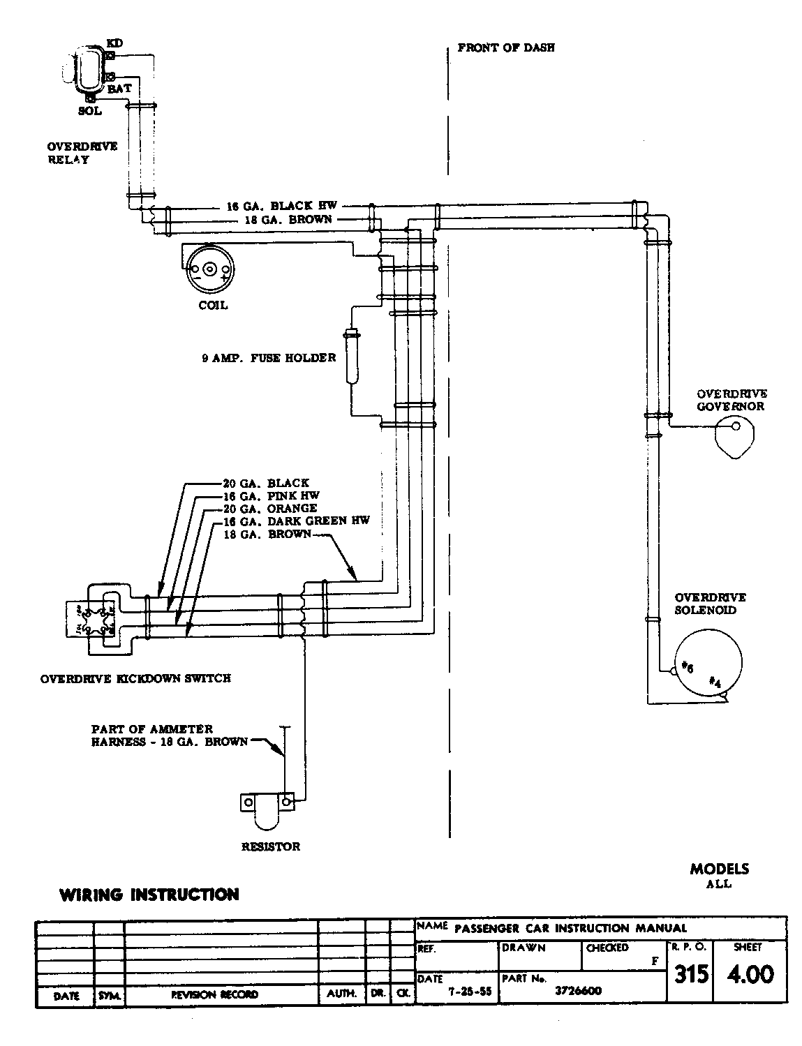
Send a PM to 1oldtimer. He is very helpful. With the system that he used you are basically putting it into overdrive when you want to as well as taking it out. It seems pretty straightforward. If you look at the OEM wiring diagram you will see the biggest wire is 16 ga. Also the factory used a 9 amp fuse. Todd
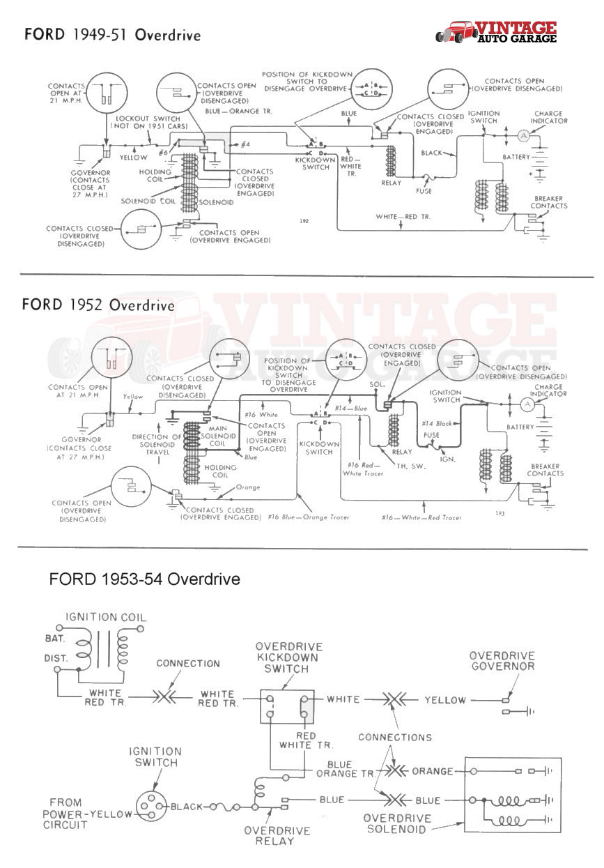
The Borg Warner Overdrive Transmission was offered as an option by eleven different car companies. And as you might expect, each of those car companies developed their own wiring diagram for the Borg Warner Overdrive. They added extra relays, switches etc, nothing that improved or affected how the overdrive itself worked. ...
Borg-Warner Relay / Kickdown Switch / Solenoid / Install Instructions: The enclosed overdrive parts are an exact replacement of the original factory Borg Warner overdrive parts. Included, as part of these instructions is a picture-wiring diagram to show you how everything is to be wired. In some applications there may
Now available an exact reproduction of the original Borg Warner overdrive relay. This is an exact reproduction of the overdrive relay used by all eleven of the car companies that offered the Borg Warner electric overdrive as an option from the late 1930 thru the early 1960's.. Complete wiring instructions included.
THE WARNER AUTOMATIC OVERDRIVE FOREWORD Material contained in this Instruction Manual re~ loles only to P'St-wor Overdrive types (Worner R-lO and R-Il) as used on the following makes 01 cars: Ford M. rauy Frazer Ncub Hudson Packard Kaiser Studebaker Lincoln W illy. While the actual details of construction may diller ...
1) Their were 11 different wiring diagrams for the Borg Warner overdrive transmission BESIDES the simple one I provide to you in my overdrive book and in the instructions that are included with the overdrive parts you buy from me. I believe simple is good so that is why I include the original Borg Warner wiring instructions.
the the overdrive lover, B. ELECTRICAL 14. a. While the of just may be considered working of its is by system, This system 01 by a the electrical practically of with there The wiring circuit wiring in the (Fig. S) applies K Willys and Nash (the With relay 1949 that the and to the Ignition switch, on the 1949 switch
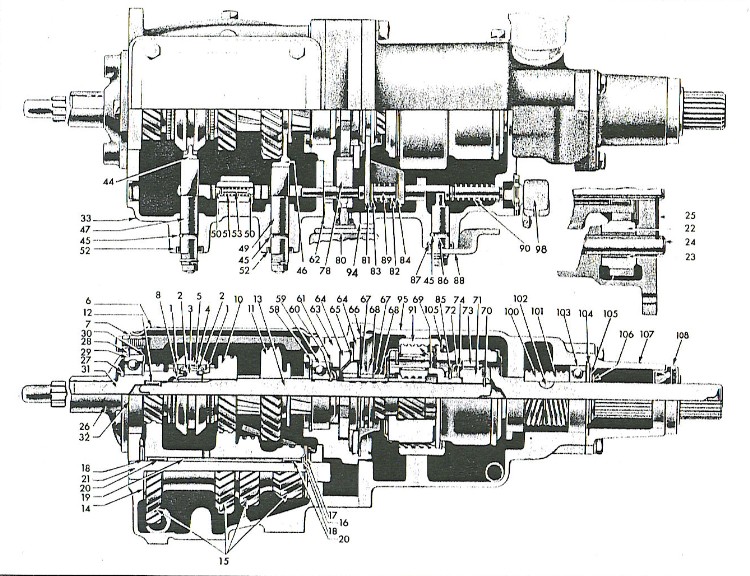
Exploded Or Cross Section Illustration Of Governor For Borg Warner Overdrive The 1947 Present Chevrolet Gmc Truck Message Board Network
Most of the other Borg-Warner overdrive units you will find are either R-10 or R-11 units. These could easily be bolted onto the tailshaft of any standard transmission of that era. There were four main electrical parts that activated these overdrive units: the relay, the switch, the solenoid and a governor; however, the solenoid was usually the ...
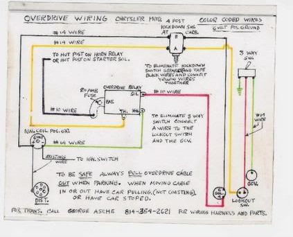
52 56 Borg Warner R10 Plymouth Overdrive Wiring Schematic Individual Member Photo Albums P15 D24 Com And Pilot House Com
Borg Warner Overdrive Wiring Diagram. Collection of borg warner overdrive wiring diagram. A wiring diagram is a streamlined standard photographic depiction of an electrical circuit. It reveals the parts of the circuit as simplified shapes, as well as the power as well as signal connections in between the gadgets. A wiring diagram normally offers details…

Garage Tech With Randy Rundle Yet More Borg Warner Overdrive Information Solenoid And Relay Part Number Id







0 Response to "35 borg warner overdrive wiring diagram"
Post a Comment